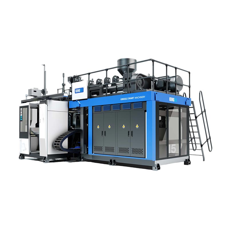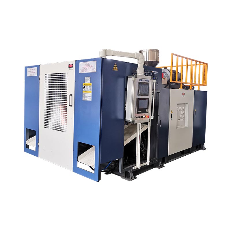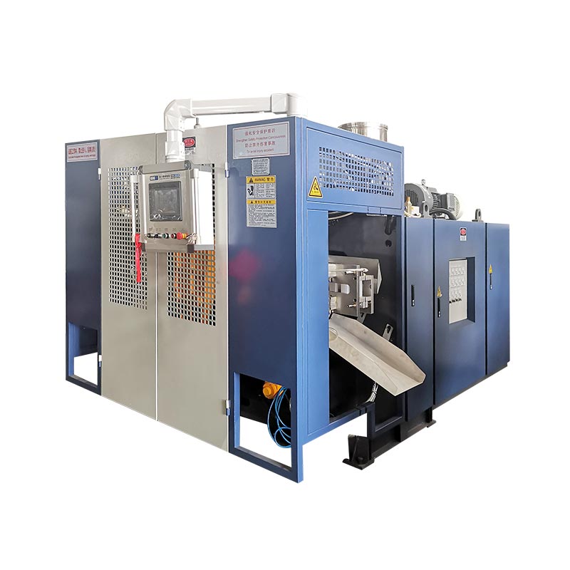
The HMI is the operator's view of the process, not the process itself. Read set values, actual feedback, machine status, and alarm history together before changing a recipe.
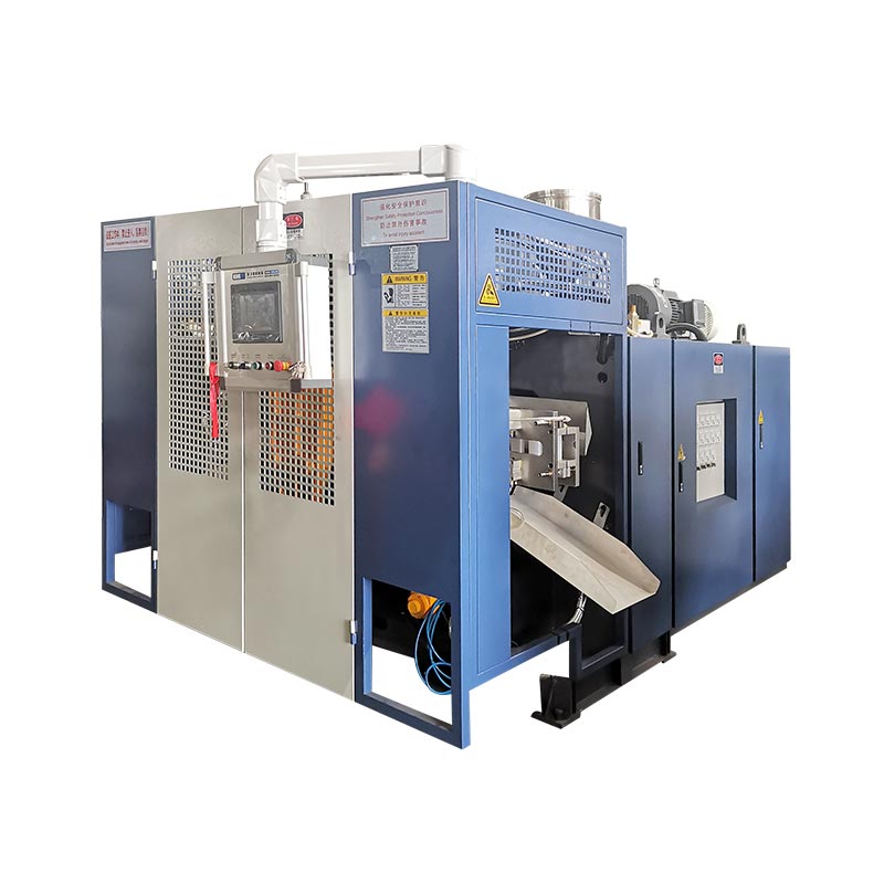
What the main HMI screens are designed to show
Screen names and layouts vary by machine, PLC program, options, and controller version. The underlying jobs are similar: select a mode, command an action, set a target, display feedback, show the sequence state, and tell the operator why the next action is blocked.
| Screen group | Typical information | Operator question |
|---|---|---|
| Main / status | Mode, cycle state, active alarms, major positions and production status | What is the machine doing now? |
| Manual operation | Mold, blow pin, core pull, carriage, robot, extrusion and auxiliary commands | Can this mechanism move safely and does it respond? |
| Temperature | Set value, actual value, heater status, high/low deviation | Is the melt system stable and ready? |
| Time settings | Delays, blow time, cooling time, movement timing and sequence windows | Is the step starting and ending at the intended point? |
| Pressure and speed | Commanded pressure or speed for selected hydraulic movements | Is the motion recipe suitable for this mold and step? |
| Function selection | Installed or enabled options and automatic sequence choices | Is the program waiting for an option that is not in use? |
| Input / output | Sensor and switch states; PLC output commands | Does the controller see the required condition and issue the command? |
| Alarm history | Active and previous alarms with time or order | Which fault occurred first? |
| Position / calibration | Platen or accumulator position, reference values and calibration fields | Does displayed position match physical position? |
| Wall-thickness control | Profile points, die-gap command, file functions and tracking | Does the profile align with the parison and part? |
Use the parison programming guide for the wall-thickness screen. This article focuses on the wider machine sequence.
Read the set value and actual value as a pair
A set value is a request. An actual value is feedback. When they do not agree, changing the request may hide the symptom without locating the fault.
For a temperature zone, first check whether the heater output is being commanded. If the set value is above the actual value but the output remains off, inspect permissives, alarm state, output logic, wiring, contactor or solid-state relay as applicable. If output is on but temperature does not rise, inspect the heater circuit and sensor location. If actual temperature overshoots, check tuning, sensor contact, switching hardware, cooling and recent recipe changes.
The same logic applies to position. A mold-open command is not proof that the platen moved. Compare command status, sensor feedback, hydraulic pressure, interlocks and the physical mechanism.
A seven-step alarm troubleshooting sequence
- Make the area safe. Stop automatic motion if the condition could damage equipment or expose a person. Follow the plant's approved procedure.
- Record the first alarm. Photograph or write down the message, time, mode, product, recipe, cycle step and any preceding event. Later alarms may be consequences.
- Do not reset immediately. A reset can erase the best clue. Read the alarm history and note which condition failed first.
- Identify the missing condition. Determine whether the sequence is waiting for temperature ready, guard closed, mold position, accumulator position, air pressure, hydraulic pressure, material, robot home, or another permissive.
- Compare HMI status with the machine. If the screen says a limit switch is off, inspect the device, target, cable and alignment. If the screen says it is on but the physical state disagrees, stop and investigate.
- Use manual mode only within procedure. Jog one mechanism at a time, with the correct area clear and all required safeguards active. Do not use manual commands to defeat an unresolved interlock.
- Verify the repair. Clear the cause, reset once, run a controlled manual check, then observe several automatic cycles before returning the machine to normal production.
How input and output screens narrow the fault
An input screen shows what the PLC receives from sensors, switches and external systems. An output screen shows what the PLC commands. Together, they help separate a sequence problem from a field-device problem.
| Observation | What it suggests | Next inspection |
|---|---|---|
| Physical sensor changes, input does not | Sensor, alignment, supply, wiring or input channel problem | Inspect the device and circuit using the electrical drawing |
| Required input is present, output never turns on | Another permissive, mode, timer, alarm or sequence condition is blocking the command | Review the sequence state and all related conditions |
| Output turns on, actuator does not move | Output device, valve, drive, hydraulic/pneumatic supply or mechanical restriction | Check command at the field device and inspect the energy path |
| Movement occurs, position never confirms | Limit switch, transducer, target, calibration or input feedback problem | Compare physical position with the feedback value |
| Alarm repeats at the same cycle point | Repeatable timing, position or process condition | Trend the related value and inspect the exact sequence transition |
Force-output functions, if present, belong to trained maintenance personnel. Energizing an output outside the normal sequence can create unexpected movement or defeat process interlocks.
The factory view: control the recipe, not just the machine
Many recurring “machine faults” begin as undocumented recipe changes. A second shift inherits a different temperature, delay, speed, pressure or profile but has no record of why it changed. The alarm becomes the first visible consequence.
A practical factory record includes product and mold number, machine model, material grade, approved recipe revision, operator, date, change reason, old value, new value, measured result and approval. Protect master recipes and let operators adjust only the fields required by their role.
Back up stable files after commissioning and after an approved process change. If a value has no documented unit, safe range or function, confirm it with the electrical and process documentation before editing it. Kinggle's current after-sales service page also describes training and preventive-maintenance support; machine-specific support should use the serial number and actual software version.
Frequently asked questions
Why will the machine not start in automatic mode?
The sequence may be waiting for a safety, temperature, position, pressure, material, robot, or mode condition. Read the first active alarm and check the related inputs instead of repeatedly pressing start.
Can I reset an alarm and continue production?
Only after the cause is understood, the area is safe, and the relevant condition has been restored. Repeated resets can hide an intermittent fault or cause equipment damage.
What is the difference between an input and an output?
An input is a signal the PLC receives, such as a limit switch or pressure condition. An output is a command the PLC sends, such as energizing a valve, heater or drive control.
Why is actual temperature different from the set temperature?
The zone may still be warming, cooling, disturbed by material flow, limited by a fault, or affected by a sensor, heater, switching or tuning problem. Check output status and the physical zone before changing the set value.
Are all Kinggle HMI screens identical?
No. Screens and available functions vary with machine model, options, PLC program, wall-thickness controller and software revision.