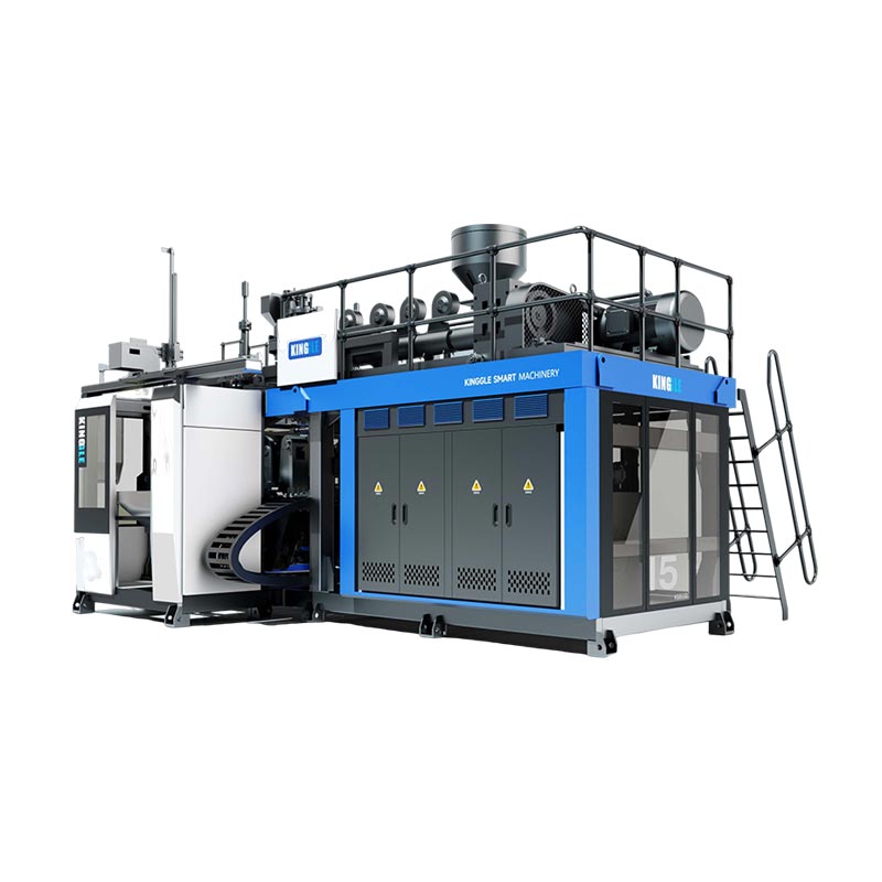
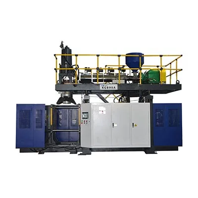
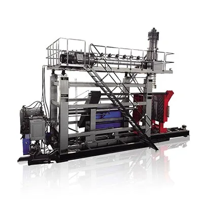
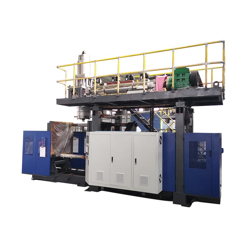
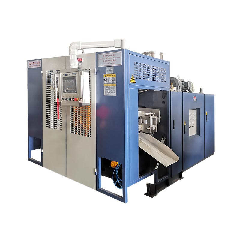
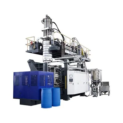
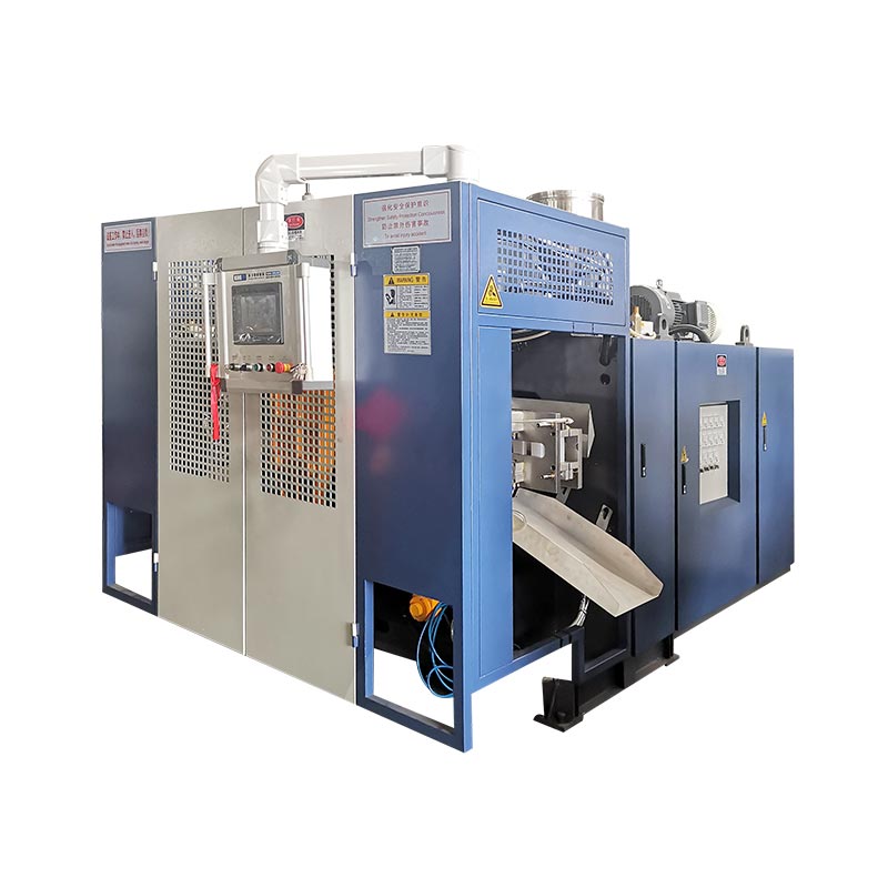
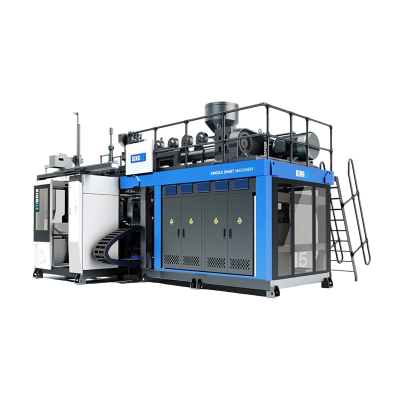
A servo hydraulic blow molding machine uses a servo-controlled motor-pump package to supply hydraulic power according to the machine's operating demand. Choose it by the movements, pressure-flow requirements and accepted-product results it must deliver, rather than a servo label or an unsupported energy-saving percentage. The decisive evidence is a controlled production trial with clear measurement boundaries.
A purchase comparison becomes misleading when three different questions share one answer: what powers the pump, what moves the mold, and what controls the part. A servo motor can improve how a hydraulic supply responds. It does not turn a hydraulic cylinder into an electric actuator, remove the cooling requirement, or establish the bottle's finished wall thickness.
Keep these checks on the purchasing shortlist:
- Identify the drive type and control scope of each machine axis.
- Read pump motor power separately from extrusion and total machine demand.
- Review simultaneous movements, not only individual maximum ratings.
- Test warm production with the actual mold, resin and acceptance rules.
- Require diagnostic records, recoverable settings and service documents.
Start with what the servo system actually controls
In a servo-hydraulic system, the electric drive and motor control the pump that supplies hydraulic power. The machine's hydraulic circuit then distributes that power to the relevant actuators. Ask which variable the control loop regulates: supply pressure, commanded flow, axis position, or a combination. These are different control tasks, even when a quotation calls all of them "servo control."
Bosch Rexroth describes its Sytronix variable-speed drives as motor-pump combinations that match connected-load demand and reduce demand during idle phases. That establishes the operating principle. It does not establish which Rexroth components, sensors or software a particular Kinggle build uses, or what savings that build will achieve.
The first purchasing document should therefore be an axis schedule. List mold opening and closing, carriage travel, blow-pin movement, take-out and any accumulator discharge movement that applies. Beside each movement, record its actuator and control method. If two movements share one hydraulic supply, make that relationship visible. If a separate drive controls extrusion, keep it separate from the hydraulic package.
Supply control is not the same as part control
A pressure-controlled pump can support repeatable motion, but a pressure value does not prove a cylinder reached its commanded position. Likewise, an encoder on the pump motor describes that motor's movement. It does not automatically measure platen position, mold parallelism or the finished product's wall thickness. The quotation should identify the feedback used for each promised function.
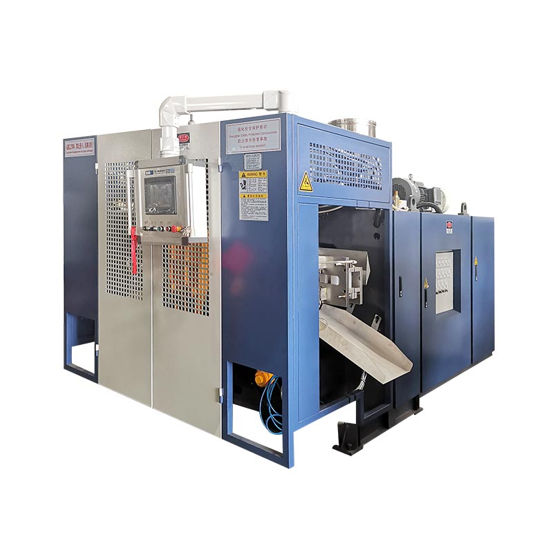
Kinggle's KGB2L product page lists a hydraulic differential design, a servo oil-pump motor and a Mitsubishi PLC. Those items describe different parts of the machine. A PLC is the sequence controller, not evidence of all-electric motion. For a broader process overview, the blow molding machine guide explains where extrusion, clamping and blowing fit together.
A useful servo specification names the controlled function and the evidence that verifies it. A component brand or a motor badge alone is not an acceptance criterion.
Read the published numbers without mixing their meanings
Kinggle's small-bottle and accumulator machines provide useful examples of servo-hydraulic equipment at different scales. The figures below come from the linked model pages. They are published configuration references, not measurements from one shared production trial. They should guide an engineering discussion rather than rank these machines against each other.
| Model and source | Maximum container capacity | Clamping force | Servo oil-pump motor | Published pump value |
|---|---|---|---|---|
| KGB2L | 2 L | 40 kN | 11 kW | 80 L/min |
| KGB90A | 60 L | 280 kN | 18.5 kW | 150 L/min |
| KGB100B | 120 L | 440 kN | 25 kW | 200 L/min |
Sources: the three linked Kinggle specification tables. The pages label the L/min values "servo pump displacement"; L/min is a flow-rate unit, unlike displacement per revolution. Confirm the pump's actual displacement, speed range and rated operating conditions in the selected build documentation.
The KGB2L has a single-station mold-shifting arrangement. The KGB90A and KGB100B pages describe accumulator-head machines with oil-cylinder mold locking and hydraulic servo systems. Their container sizes and clamping demands differ substantially. The 25 kW pump motor on the KGB100B is therefore not evidence that it is less efficient than the 11 kW motor on the KGB2L.
Separate the pump motor from the extruder motor, too. The KGB100B table lists a 55 kW extruder motor alongside its 25 kW servo oil-pump motor. These ratings belong to different loads. Neither number represents the electricity consumed while producing a particular accepted container.
Two catalogue labels deserve special attention
The KGB2L page lists 600 PC/HR under "Output(dry Cycle)." Treat that as a dry-cycle reference, not a promise of 600 accepted bottles per hour. Production output depends on the actual bottle, mold, resin, cooling and finishing sequence. A fast empty movement cannot establish those results.
The same page lists "Average energy consumption" as 12 to 18 kW. Those units describe power, not energy accumulated over time. Do not convert the range into kWh per bottle without a matched measurement window and accepted-product count. Kinggle's energy-consumption guide explains that measurement separately.
Pressure and flow must work together through the required sequence
A pump's headline flow value does not tell a buyer how much flow remains available at the required pressure. Motor power, pump characteristics, oil condition and circuit losses constrain that operating point. Review the pressure-flow envelope for the actual duty cycle, including the time spent at each condition. A list of separate maximum values is not enough.
Parker's T6 pump catalogue gives a selection routine that checks displacement, speed, leakage, available flow and power loss. Its worked method distinguishes theoretical flow from effective flow and adds losses to the theoretical power requirement. The method is useful here; its particular pump ratings should not be transferred to a Kinggle machine.
A short calculation exposes the missing information
The ideal hydraulic power associated with a pressure difference and delivered flow is:
For an illustrative operating point of 100 bar and 60 L/min, the ideal hydraulic power is 10 kW. At 200 bar with the same flow, it is 20 kW. These are constructed examples, not Kinggle operating pressures or test results. Actual drive input must also cover the relevant losses; an electrical rating cannot be treated as ideal hydraulic output.
The calculation explains why an 11 kW pump motor and an 80 L/min catalogue value do not establish that the pump delivers 80 L/min at every pressure. The supplier needs to show the operating conditions that can occur together. Ask for continuous and intermittent limits, permissible speed range, power limitation behavior and the consequences of reaching a limit.
Review overlapping movements before increasing pump size
If carriage motion and another hydraulic axis overlap, their combined demand may differ from their individual demand. The circuit may prioritize an axis, temporarily reduce speed, or separate supplies. Ask the supplier to explain the chosen strategy and demonstrate it during the specified sequence. Do not assume every quoted movement reaches its individual maximum speed simultaneously.
Clamping force needs a separate review of the mold and clamping mechanism. A pump pressure reading is not a direct measurement of usable force at the tooling, nor evidence of platen parallelism. Compare the ordered mold thickness, opening stroke, mounting arrangement and pinch-off requirement with the approved clamping configuration.
Keep blowing air out of this calculation. The KGB100B page's 0.8 MPa value is labelled blow pressure. It is not the hydraulic system's pressure rating. Kinggle's utility-requirements guide separates electrical supply, compressed air and cooling water so those systems can be reviewed on their own terms.
Follow the cycle instead of judging one impressive movement
A short demonstration can make a machine look responsive while concealing where production time is lost. Record the actual sequence from parison readiness to the next accepted part. Include the permissions that allow each movement to begin. A hydraulic axis waiting for a robot or a cooling condition may already be fast enough; accelerating it would not shorten the complete cycle.
During fast travel, observe whether the motion reaches the programmed position smoothly and decelerates before contact. During mold locking, examine pressure build-up and the actual clamp condition. During holding or cooling, check which hydraulic loads remain active and how the supply responds. At opening and take-out, watch for interference, delayed permissions or repeated corrections.
Record motion times and quality results together. A shorter mold-close time has little purchasing value if it produces an unstable pinch-off or forces a later adjustment. Equally, a quiet power unit is not enough if a motion slows as the oil reaches its normal operating condition. The trial must connect the movement to the part that follows it.
Keep parison control on its own diagnostic path
A servo hydraulic extrusion blow molding machine may have a separate wall-thickness control system. Kinggle's KGB100B page lists a MOOG 100 thickness controller. That does not make pump-speed control and die-gap programming interchangeable. They address different parts of the process, and a test should preserve both sets of settings.
If wall distribution moves from cycle to cycle, compare the parison command and available feedback with extrusion stability, shot consistency and timing. If one side stays thin, inspect centering and alignment before increasing the full profile. Kinggle's parison programming guide explains why software edits cannot reliably repair a mechanical or process fault.
The practical purchase priority is a repeatable sequence that produces acceptable parts. Peak axis speed belongs underneath that goal. Require event records that reveal which stage changed when output or quality changed, rather than accepting a single total-cycle number with no breakdown.
Compare hydraulic, servo-hydraulic and electric drives by the application
Drive labels are useful only after the motion architecture is clear. "Hydraulic" describes how power reaches the actuator. "Servo-hydraulic" adds a description of control, often at the motor-pump package. "All-electric" should identify electric actuation for the stated machine movements. A machine can also combine different drive types, so an axis schedule is more informative than one label.
| Drive description | What to establish | Evidence to request |
|---|---|---|
| Conventional hydraulic | Pump type, motor operation and method of controlling or unloading supply | Circuit, duty conditions, heat management and a matched production test |
| Servo-hydraulic | Which motor-pump functions vary with demand and which axes share the supply | Pressure-flow limits, control scope, feedback and cycle-event results |
| Electric motion system | Which axes use electric actuation and whether any hydraulic functions remain | Axis list, force/speed limits, mechanical service needs and production results |
Manufacturer documentation shows why that distinction matters. Bosch Rexroth's variable-speed hydraulic drive description explains demand-based motor-pump operation. By contrast, Bekum's electric-machine description explicitly identifies electric clamping, extruder lift and take-out. The latter is a definition example, not a recommendation to replace Kinggle's hydraulic models or evidence of a Kinggle electric offering.
Do not assume a conventional hydraulic package runs at full load through every pause. Its pump and unloading arrangements need to be checked. Likewise, do not assume a servo package eliminates cooling, oil care or every hydraulic loss. Bosch Rexroth describes reduced heat input and cooling demand for its variable-speed systems, but that is not a claim that the complete production cell needs no cooling.
For procurement, shortlist the machine that fits the mold and required force, completes the sequence, and can be maintained locally. Then compare measured results on the same product basis. If hygiene rules restrict hydraulic oil near the product, define the restricted area and permitted arrangements explicitly. If service access is difficult, inspect component replacement paths before choosing the package.
A drive architecture earns its place through product fit and documented results. Choosing the newest label before defining the part creates an expensive comparison with no reliable decision basis.
Make the acceptance test answer the purchasing question
A servo-hydraulic acceptance test should establish whether the ordered package completes the required production sequence under defined conditions. Agree the product drawing, mold revision, resin grade and accepted-part tests before running. Identify the actual machine build and software revision. Changing the test article midway can make apparently better energy or cycle results impossible to compare.
Use separate records for hydraulic-drive behavior and total machine energy. A pump-drive sub-meter can help explain where the hydraulic package uses electricity. The incoming machine meter may also capture extrusion, heaters and installed auxiliaries. Neither necessarily captures the compressor or chiller. Record the boundary beside the result instead of describing every reading as "machine consumption."
EUROMAP 46.2, Version 1.0, specifies product-related energy measurement for an extrusion blow molding machine with a given mold and customer-defined product requirements. It calls for stable automatic operation, barrel conditions and oil temperature before measurement. Its measurement conditions include at least 10 minutes and at least 15 cycles. These are energy-measurement requirements, not a complete reliability or shipment-acceptance test.
Use the recommendation's defined conditions when that method forms part of the purchase agreement. Add a separate run and sampling plan appropriate to the product and production risk. A longer endurance requirement needs its own agreed duration, stops policy, inspections and deviation handling; it should not be implied by the energy test alone.
- Freeze the test configuration, product identity, utilities and quality limits.
- Stabilize the machine according to the agreed method and operating instructions.
- Record the normal production sequence, including overlapping motions and pauses.
- Measure electricity and accepted output over the same defined window.
- Inspect samples against the agreed dimensions, wall locations and functional tests.
- Reproduce permitted stop-and-restart conditions and record recovery behavior.
- Close deviations with supporting results and save the approved settings.
Energy per accepted part is measured kWh divided by accepted parts from that same window. If the trial is for only the machine boundary, name the metric accordingly. This purchasing measure should not be confused with EUROMAP's product-mass denominator, and it should not hide rejects by counting every molded item as accepted output.
Kinggle's factory acceptance test guide shows why a bare "passed" result is weak evidence. Apply that logic to the drive package: state what was observed, under which condition, against which limit, and what happened when the sequence changed.
A serviceable system separates hydraulic faults from process faults
Choose a package that lets maintenance identify a problem before adjusting settings. A servo alarm, a pressure fluctuation and a thin bottle wall are different observations. They may be connected, but treating them as one "hydraulic problem" can lead to unnecessary changes. Start with the recorded event and compare it with the last approved production baseline.
| Observation | Compare first | Avoid this shortcut |
|---|---|---|
| Motion slows after warm-up | Actual oil condition, pressure/flow response, cooling and recorded axis time | Increasing every pressure setting |
| Pressure changes while movement stalls | Command, available feedback, sequence permission and circuit condition | Assuming the motor is undersized |
| Cycle time rises but axis times stay stable | Cooling, parison readiness, take-out and downstream waits | Buying a faster pump to fix a different bottleneck |
| Wall distribution changes | Parison profile, extrusion stability, tooling and relevant actuator feedback | Treating pump speed as a wall-thickness recipe |
These checks organize the investigation; they do not replace the supplier's fault-finding procedure. Physical inspections, electrical measurements and hydraulic adjustments require authorized personnel. Machine instructions should state how to isolate electrical, hydraulic and pneumatic energy and deal with retained loads. Stopping a motor alone does not establish that a hydraulic circuit is safe to open.
OSHA's hazardous-energy guidance identifies hydraulic and pneumatic energy alongside electrical and mechanical hazards. Use the applicable local requirements and the machine-specific isolation procedure. Never bypass an interlock or loosen a live connection to investigate a pressure problem.
Inspect the service package before shipment
Require an indexed hydraulic circuit, electrical drawings, component part numbers, approved oil and filter specifications, maintenance instructions and a documented settings backup. The buyer should know how to replace a drive or controller without losing the approved configuration. Agree who can access protected parameters and how a changed setting will be recorded and reversed.
Check cabinet access and cooling arrangements against the plant environment. Inspect whether maintenance can reach service points without removing unrelated equipment or entering a hazardous area. Spare-parts availability deserves a concrete discussion about identifiers and supply arrangements, not a promise that familiar component brands eliminate downtime.
A useful handover includes the accepted baseline, the alarm list and the evidence needed for remote diagnosis. That allows the factory to report an identifiable condition instead of sending a video of an unexplained stop.
Put the drive system into the purchase specification
A quotation should connect the drive package to an approved product and production target. Begin with the part drawing, finished weight, wall requirements, resin grade, tooling arrangement and planned shifts. Then define the movements and operating conditions the machine must complete. This gives the supplier a duty to solve rather than a request for a particular motor size.
For a small bottle, the KGB2L provides a published small-capacity starting point. For larger industrial products, the KGB90A and KGB100B provide accumulator-machine references. Select among them through the complete tooling and process requirement, not nominal container volume alone.
The drive schedule should state the hydraulic supply arrangement, pump and motor identity, controlled variables, required feedback and permissible operating envelope. Attach the agreed sequence and identify which actions may overlap. Include oil cooling and plant conditions because the equipment must work in the receiving factory, not only in the supplier's test area.
- Define acceptable product output separately from dry-cycle performance.
- Specify the energy boundary and the agreed measurement method.
- State how cycle events, deviations and sample identity will be recorded.
- Identify the drawings, software backups and maintenance files supplied at handover.
- Agree the permitted restart scenarios and evidence required to accept them.
Keep performance and commercial terms explicit. If energy reduction is a purchasing condition, define the comparison baseline and test article. If a guaranteed output matters, state the accepted-part criteria and trial conditions. A general promise of fast response cannot settle a dispute about a slow production line.
The strongest proposal will explain why its selected pressure-flow package suits the mold and sequence, how the test will prove that choice, and how the receiving factory can preserve the result. Buy that engineering fit. A servo label is only the beginning of the assessment.
To discuss a Kinggle configuration, send the product drawing, resin grade, mold information and target accepted output through the Kinggle project inquiry page. Include the receiving factory's voltage, cooling conditions and downstream equipment so the drive system can be reviewed as part of the production cell.
Email: sales@kinggle.com · Telephone: +86-574-87103665
Frequently asked questions
Is a servo hydraulic blow molding machine all-electric?
No. A servo-hydraulic machine uses an electric servo drive to control a hydraulic pump while hydraulic oil still transmits power to the relevant actuators. An all-electric motion system uses electrical drives for the specified machine movements. Check the drive type of each axis, including mold close, carriage travel and take-out, rather than relying on a general machine label.
Does servo control automatically improve bottle wall thickness?
No. Pump control and parison programming perform different jobs. A stable hydraulic supply can support an actuator that depends on it, but wall distribution also depends on the die-gap profile, tooling alignment, extrusion stability, resin and part geometry. Diagnose command and feedback behavior before changing the profile or increasing overall part weight.
Can servo oil-pump motor power predict the electricity bill?
Not by itself. The motor rating describes one installed component, not total machine energy over a production shift. Measure kWh at an identified boundary and count accepted output over the same window. Include compressor and cooling energy separately when they fall outside that boundary. Compare the same product and quality requirements.
What should a buyer compare between two servo-hydraulic quotations?
Compare the axis list, clamp and mold fit, required pressure-flow operating points, simultaneous movements, oil cooling, control diagnostics and service documents. Then compare trial results under matched product conditions. A larger pump or a smaller motor is not automatically the better choice. The package must complete the agreed sequence without losing acceptable output.
Can an existing hydraulic blow molding machine be upgraded with a servo pump?
A retrofit may be feasible, but it needs an engineering review. Check the pump, motor and drive combination, valves, pressure limits, cooling, control interface and safety functions. Also identify the existing production bottleneck. Replacing the pump drive cannot remove a mold-cooling or extrusion limit, and the modified machine needs a defined commissioning and acceptance plan.