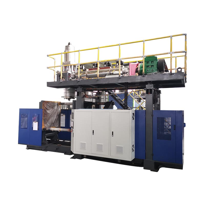
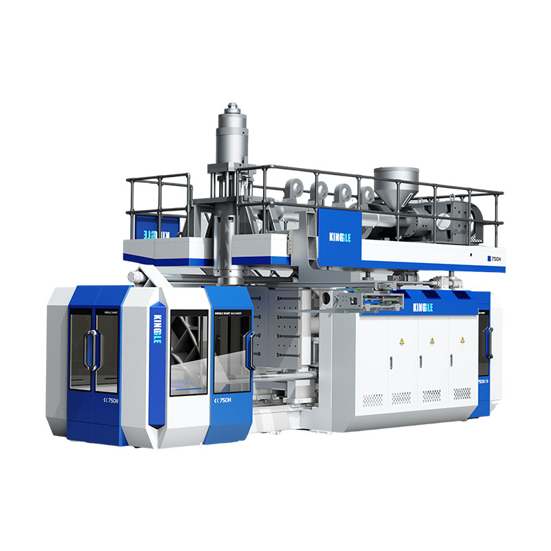
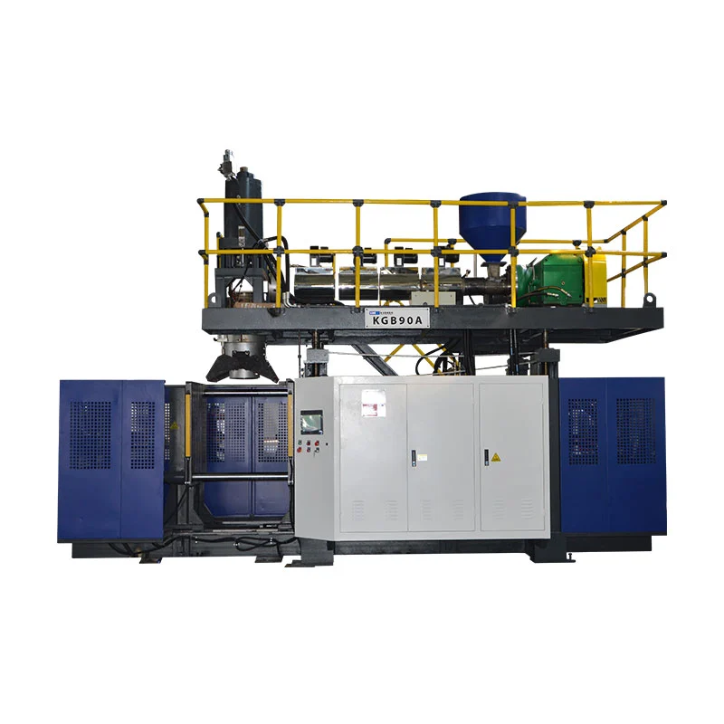
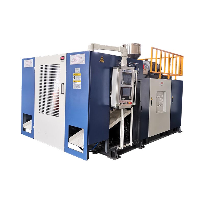
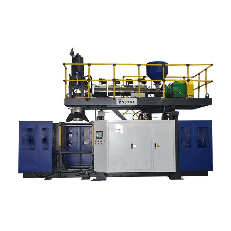
The same visible defect can come from resin, parison formation, tooling, air, cooling, machine condition or an undocumented recipe change. This guide helps a production team find the first useful evidence before changing settings.
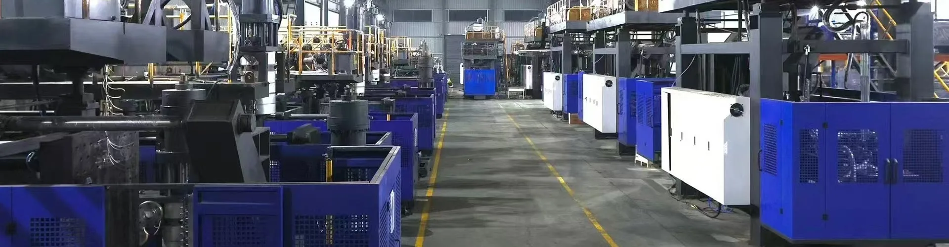
Terminology note: International production teams may call the same topic blow moulding defects, blow moulding problems and solutions, plastic bottle defects or blow molded part defects. The spelling and part name change; the evidence-based diagnostic method does not.
Start with a four-layer diagnostic workflow
A list of possible causes is useful, but it can also encourage random adjustment. A better sequence narrows the fault from the finished part back through the process. The resin supplier guides from LyondellBasell, Formosa Plastics and Teknor Apex all show that one symptom may have several process, material and tooling causes.
Ask four questions before touching the recipe
- Is the defect local or global? One side suggests die centering, mold alignment, cooling imbalance or localized venting. Every cavity or every part suggests a shared material, temperature, pressure, utility or sequence issue.
- Is it repeatable or intermittent? A defect at the same position every cycle points toward geometry, tooling or a synchronized process event. A moving defect points more often toward unstable extrusion, contamination, utilities, sensor feedback or shot variation.
- What changed immediately before it appeared? Check material lot, regrind percentage, color, recipe revision, mold service, heater repair, water circuit, air demand, shift handover and start-up condition.
- Does the measurement agree with the visual judgement? A container can look acceptable while minimum wall, weight, neck dimension, leak performance or top load has moved outside the approved requirement.
Extrusion blow molding defect troubleshooting matrix
Use this table as a route to the first checks, not as a universal setting sheet. Resin grade, part geometry, die head, mold, machine type and quality specification determine the correct operating window.
| Defect or search term | Possible cause layers | First evidence to check | Corrective direction |
|---|---|---|---|
| Excessive flash | Too much material at the pinch, mold not fully closing, clamp issue, worn or damaged pinch-off, alignment or timing | Flash location and thickness, mold-close position, clamp feedback, part weight, pinch-off condition | Correct closure or tooling condition; then redistribute material rather than reducing the entire part blindly |
| Thin or weak pinch-off | Melt too hot, insufficient material at weld, unsuitable pinch geometry, excessive or early pre-blow | Weld section, parison position, temperature actuals, pre-blow timing, approved tooling condition | Restore the stable thermal and timing baseline; inspect the mold before adding global weight |
| Pinch-off cutting or split | Cold parison, sharp or damaged pinch, fast mold close, misalignment | Part with flash still attached, cut location, mold movement and tooling edge | Correct physical damage/alignment and verify mold-close sequence; make only controlled thermal changes |
| Uneven wall thickness | Profile position, die centering, parison sag, unstable output, mold shift, asymmetric cooling or stretch | Fixed wall map over several cycles, part weight, die gap feedback and defect side | Separate a local profile need from mechanical asymmetry; use the approved wall map |
| Thin corners, shoulder or handle | High local stretch, parison too small or misplaced, insufficient programmed material, early contact | Minimum-wall location, parison diameter/length, profile-to-part alignment | Place material at the demanding zone and confirm parison position before increasing total weight |
| Parison sag or drawdown | Low melt strength, excessive temperature, long hang time, heavy parison, resin behavior | Parison length and shape against time, actual melt condition, drop/transfer timing | Shorten unsupported time or stabilize melt and output within the approved process window |
| Parison curl or hooking | Die temperature imbalance, misalignment, contamination at die lip, uneven flow | Direction of curl, warm-up state, die-lip condition and head-zone actuals | Allow stable warm-up; inspect and clean using the approved procedure; correct alignment rather than compensating at the mold |
| Rough parison, melt fracture or orange peel | Flow instability, unsuitable shear rate, temperature condition, die land or rough mold/poor venting | Whether roughness exists on the free parison, extrusion rate, mold surface and vents | Identify parison versus mold origin; bring the extrusion process back into a stable window |
| Bubbles or voids | Moisture/condensation, trapped gas, poor mixing, material leakage/degradation, contamination | Material handling, hopper/throat condition, bubble pattern, resin requirement and melt consistency | Remove the material-handling cause; verify mixing and equipment condition before adding back pressure |
| Black specks or burn marks | Degraded resin, dead spots, contaminated regrind, excessive residence time or incorrect shutdown/start-up | When specks began, color/regrind lot, purge condition, temperature history and downtime | Quarantine suspect material and follow the approved purge/cleaning procedure; remove the degradation source |
| Die lines or streaks | Damaged/dirty die lip, contamination, degraded material, uneven color or flow | Whether the line is fixed around the parison, die-lip inspection and material change history | Protect precision surfaces and clean by procedure; correct material blending or damage |
| Incomplete blow or poor detail | Restricted/insufficient air, leakage, poor venting, parison too cold, timing or short parison | Machine-inlet air during blowing, blow-pin seal, vents and thin/unfinished region | Restore air delivery and venting; confirm parison capture and temperature baseline |
| Blow-out | Weak or cut parison, incorrect pinch, low clamp, too much stretch, short parison or aggressive blowing | Failure origin, parison capture, pinch condition, wall map and mold closure | Correct the first physical failure; do not hide it by adding broad part weight |
| Warpage, rocker bottom or oval neck | Insufficient or uneven cooling, blocked channel, high melt heat, early ejection, uneven material distribution | Supply/return water, cavity temperature pattern, cooling time and post-ejection change | Restore balanced heat removal; then review cycle time and wall distribution |
| Leak or failed functional test | Pinch-off weakness, pinhole, thin wall, neck finish, trimming damage, contamination or test setup | Mark exact failure position; section the part; verify tester and trim condition | Trace the leak to its forming stage and repeat the defined test after correction |
Material and melt defects: follow the lot before the machine
When a defect starts after a resin, masterbatch or regrind change, preserve labels and samples before adjusting the equipment. Record the resin grade, lot, color ratio, regrind source, grinder screen, storage condition and time of change. A contaminated blend can create black specks, streaks, bubbles, die lines, poor welds and unstable extrusion. One adjustment cannot correct all of them.
Moisture is not identical across materials. Follow the resin supplier's handling and drying requirements instead of assuming every blow molding resin needs the same treatment. Condensation on cold material or in the feed area can still create a problem even when the polymer is not normally dried. The LyondellBasell troubleshooting guide identifies condensation and melt non-uniformity among possible causes of bubbles and wall defects.
Black specks, smoke and burnt material
First determine whether the defect is fixed to one flow path or distributed randomly. A fixed line can indicate a die/head location. Random specks may follow contaminated resin, regrind or degraded material released from a dead area. Review long stops, high-temperature exposure, start-up and shutdown records, then use the machine- and resin-approved purging method. Do not scrape precision die surfaces with an unapproved tool.
Color streaks and inconsistent blending
Check whether the streak follows a material change, low bulk density regrind, feeder interruption or a fixed die position. Inspect the dosing and blending record before increasing mixing energy. More back pressure can improve mixing in some processes, but it can also add shear heat and residence time. The correct response depends on the extruder, resin and established process window.
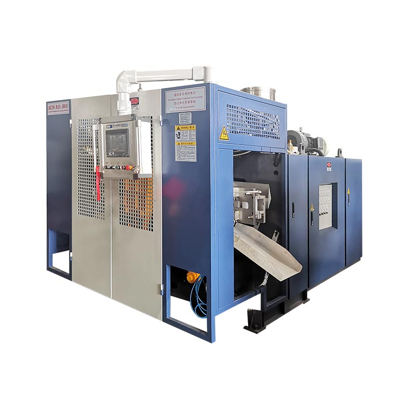
Parison defects and uneven wall thickness
The parison is already changing before the mold closes. Die swell increases its size as it exits the tooling; gravity and low melt strength can pull it downward; temperature and flow can vary around the circumference. A 2025 open-access study on parison formation using extrusion process data also treats swell, drawdown and temperature distribution as important factors. This is why a finished wall map is more useful than a single average thickness.
When the wall is thin on one side
Measure the same circumferential positions on several consecutive parts. If the thin side stays fixed relative to the mold, inspect die centering, mold position, local cooling and early parison contact. If it rotates or moves, investigate extrusion stability, material consistency and feedback. Do not offset a mechanical misalignment with a complicated profile unless the physical cause has been ruled out.
When a corner, shoulder, handle or bottom is thin
These features stretch the parison more than a straight wall. Confirm that the parison reaches the correct length and position at mold close. Then align the programmed thick section with the demanding feature. Kinggle's parison programming and wall-thickness guide explains profile position, local opening and overall scale in more detail.
When thickness changes from cycle to cycle
A profile is not the first correction for an unstable process. Compare actual temperature, extrusion output, accumulator shot or position where applicable, parison length, hydraulic behavior and die-gap command/feedback. Stabilize the process before editing many points. Save the accepted recipe as a protected revision so the team can reverse an unsuccessful change.
Flash, pinch-off failures and leaking parts
Flash is the material outside the molded cavity, commonly around the parting line, neck and bottom pinch. Some flash is inherent to extrusion blow molding and is removed downstream. The defect is excessive, asymmetric or unstable flash that affects trimming, weld quality, weight, closure or cycle reliability.
Read the flash pattern as evidence
- Flash everywhere: compare part weight, parison size, mold-close completion and clamp condition.
- Flash on one side: inspect mold alignment, parallelism, tooling condition and parison placement.
- Flash becomes thicker over time: review thermal drift, shot/output drift, wear and hydraulic condition.
- Flash tears the weld during trimming: inspect pinch-off geometry, wear, closure and trim process before changing temperatures.
A thin weld, a torn weld and a cut parison are different failure modes. LyondellBasell's guide separates these pinch-off problems because the likely remedies can point in opposite directions. Keep the flash attached to the failed sample until the failure origin has been documented.
Trace a leak to the forming stage
Mark the leak location from the tester, then section the part if the quality procedure allows it. A leak at the bottom weld leads the team toward pinch-off, material placement and cooling. A pinhole in the body leads toward a bubble, contamination, die line or local thin wall. A neck leak may involve finish formation, trimming, insert position or the test fixture. Verify the leak tester with a known reference before changing the molding process.
Surface defects: separate the parison from the mold
Observe the free parison safely from outside the guarded area. If a line or roughness already exists before mold close, investigate material, melt stability and die condition. If the parison looks acceptable but the finished surface is dull, pitted or lacks detail, inspect mold surface, vents, blowing, temperature and condensation.
Orange peel and rough surface
Possible layers include rough parison flow, poor mold venting, low or restricted air delivery, leakage around the blow pin, a cold parison or a damaged mold surface. Check the pressure at the machine during the blow event; a compressor display elsewhere in the factory does not prove that pressure and flow reach the mold at the required moment. Kinggle's utility planning guide covers the air and cooling path from plant supply to machine connection.
Die lines and fixed streaks
Mark the streak position around the part and compare it with the parison. If it remains fixed, inspect the corresponding flow path after the correct shutdown and isolation. A nick at the die lip can reproduce on every cycle. Contamination or degraded resin can also lodge in the head and release intermittently. Cleaning must protect the precision surfaces and follow the supplied procedure.
Cooling defects, warpage and dimensional drift
Warpage often becomes visible only after ejection. Compare the part immediately after mold opening, after trimming and after the specified conditioning time. A rocker bottom, oval neck or dimensional drift may follow insufficient cooling, unequal cavity temperature, a blocked water channel, high melt heat, early handling or an uneven wall distribution.
Record supply and return temperature, pressure and—when instrumentation is available—flow for the affected mold circuit. Touch is not a reliable temperature measurement and does not reveal a restricted channel. If one side of the part changes while the plant supply remains stable, investigate the local manifold, connection, channel and mold condition.
Machine, HMI and utility checks before process adjustment
The HMI shows requests, feedback, sequence state and alarms. It does not prove that a valve moved, air reached the blow pin or water flowed through a mold. Read a set value and its actual value as a pair, then compare the screen with the physical result.
| Observation | What it may separate | Next safe check |
|---|---|---|
| Temperature set value is stable but actual value drifts | Recipe issue versus sensor, heater, cooling or control issue | Review output state, alarm history and the authorized electrical/thermal inspection path |
| Air supply is normal at idle but defect appears during blowing | Static pressure versus dynamic pressure/flow limitation | Record machine-inlet pressure during simultaneous factory demand |
| Command changes but parison or part does not respond | Recipe command versus actuator, valve, calibration, sticking or feedback issue | Compare command and feedback, then escalate under the maintenance procedure |
| Alarm repeats at the same cycle step | Random event versus a missing permissive, position or timing condition | Preserve the first alarm and inspect the related inputs and physical state |
| Defect began after a saved recipe was loaded | Machine fault versus recipe/mold/material mismatch | Compare revision, units, mold identity and protected baseline without overwriting evidence |
Use the Kinggle HMI settings and alarm guide for a structured sequence. If the problem includes leaks, changing temperatures, dirty oil, restricted cooling or recurring alarms, the preventive maintenance checklist helps connect product quality with machine condition.
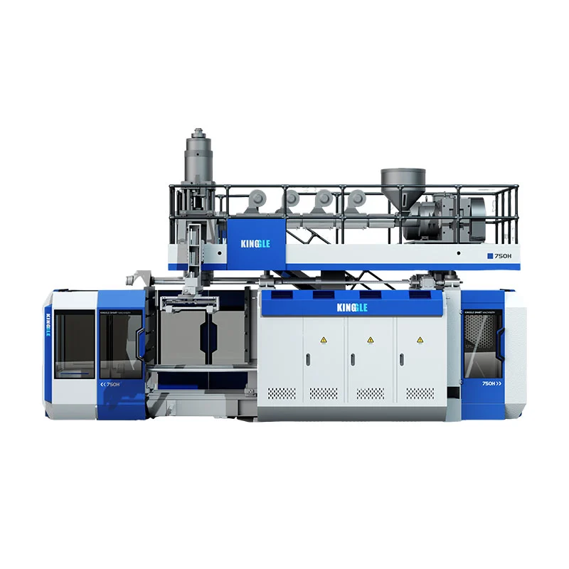
The factory view: build a defect record that another shift can use
“Adjusted temperature and now better” is not a reproducible record. A useful log connects the suspect part to a time, machine state and verified result. Photograph the defect with a scale or marked location when practical, and keep an approved good sample for comparison.
| Record field | What to capture | Why it matters |
|---|---|---|
| Identity | Date/time, machine, mold, cavity/head, product revision, operator and shift | Shows whether the fault follows equipment, tooling or a handover |
| Material | Resin grade/lot, masterbatch, regrind source and proportion, time loaded | Connects defects with a material change without guessing |
| Symptom | Exact location, frequency, first cycle, photo and retained sample | Separates a fixed defect from intermittent process variation |
| Process state | Recipe revision, actual temperatures, part weight, cycle time, parison/shot observation and first alarm | Preserves the baseline before adjustments erase evidence |
| Utilities | Machine-inlet air and water condition during production; relevant hydraulic condition | Reveals shared plant or heat-removal problems |
| Controlled change | Old value, new value, reason, person and time | Prevents several simultaneous changes from hiding the cause |
| Verification | Stable-cycle count defined by the plant, wall map, weight, dimensions and required functional tests | Proves whether the correction improved the actual requirement |
When to stop adjusting and escalate
- A guard, interlock, emergency stop or hazardous-energy control is not functioning as intended.
- A mechanical collision, unexpected movement, hot electrical condition, hydraulic leak or damaged pressure component is suspected.
- The same defect remains after the verified material, utility and approved recipe baselines are restored.
- Command and actual feedback disagree, or the process does not respond predictably to a controlled change.
- Tooling repair, calibration, program change or operation outside the approved process window would be required.
Preventing recurring defects starts before machine commissioning
For a new extrusion blow molding machine or new mold, define acceptance evidence before the trial. Provide the part drawing, resin grade, target weight, critical wall locations, neck and overall dimensions, trimming plan, leak or pressure test, visual criteria, output target and plant utilities. A useful trial report connects the accepted samples to the exact mold, material and recipe revision.
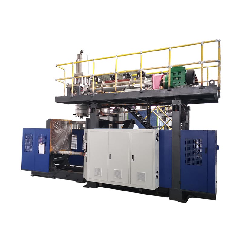
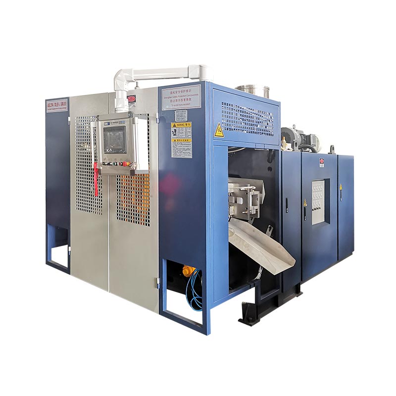
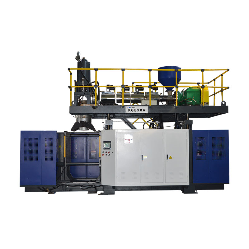
Small containers and high-output projects may fit a continuous extrusion blow molding machine. Larger or heavier parts may require an accumulator blow molding machine. The correct choice depends on the part and process package, not the defect name alone. Browse Kinggle's blow molding applications or send the actual product information for a project-specific discussion.
Frequently asked questions
What are the most common extrusion blow molding defects?
Common defects include excessive flash, weak or cut pinch-off, uneven wall thickness, thin corners, parison sag or curl, melt fracture, bubbles, black specks, die lines, incomplete blowing, blow-outs, warpage and leaks.
What causes uneven wall thickness in blow molding?
Possible causes include profile position, die centering, parison sag, unstable extrusion or shot size, mold alignment, unequal cooling and the amount of stretch required by the part geometry.
How do you reduce flash in extrusion blow molding?
First check where the flash occurs, part weight, parison placement, mold-close completion, clamp behavior, alignment and pinch-off condition. Correct a closure or tooling fault before changing global part weight.
Why are there bubbles in a blow molded part?
Possible causes include condensation or moisture, trapped gas, insufficient melt uniformity, material leakage, degraded material and contamination. Check the resin requirement and material path before changing the process.
Can parison programming fix every thin-wall defect?
No. Parison programming cannot reliably correct die misalignment, unstable extrusion, damaged tooling, poor cooling, incorrect mold position or a malfunctioning actuator.
What should be changed first during blow molding troubleshooting?
First restore and verify the approved material, recipe, utility and machine-condition baseline. After identifying the most likely layer, change one controlled variable and repeat the same part measurements.
Why does the same defect return on another shift?
Recurring defects often return when recipe revisions, material changes, utility readings, alarms and corrective actions are not recorded consistently. A shared defect log and protected baseline make the process repeatable.