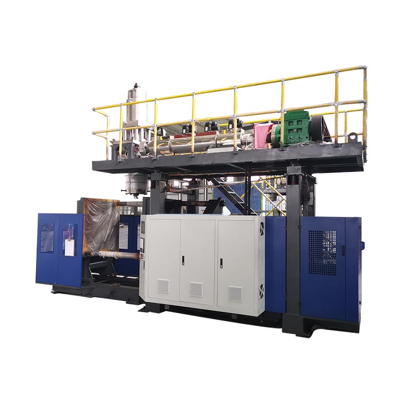
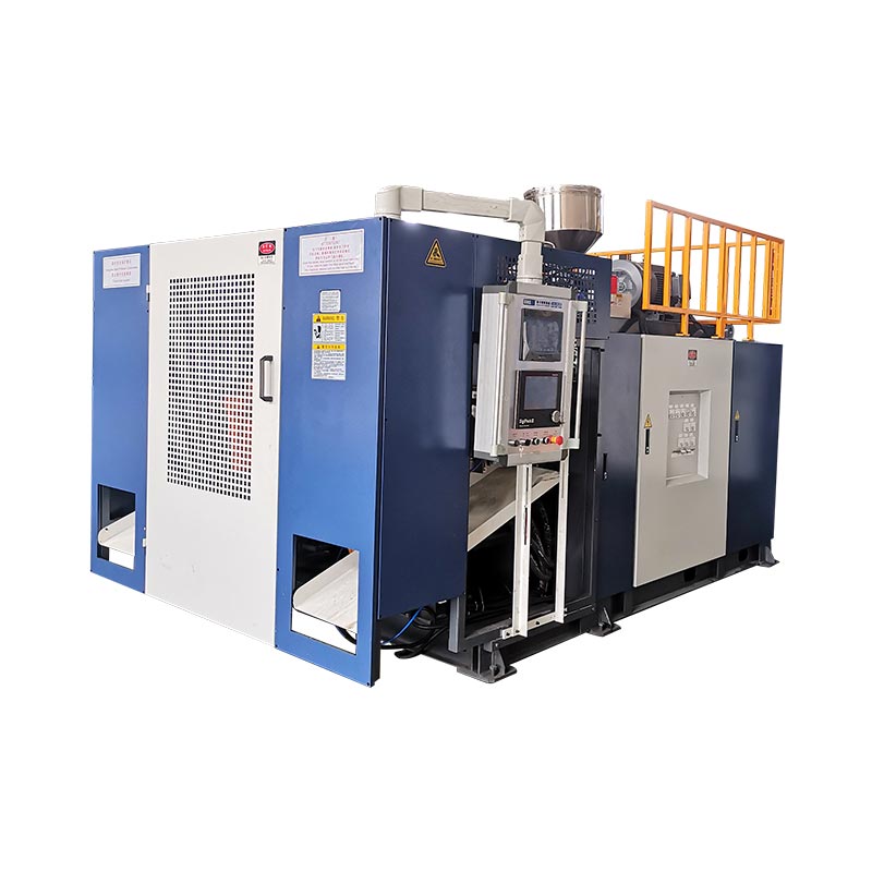
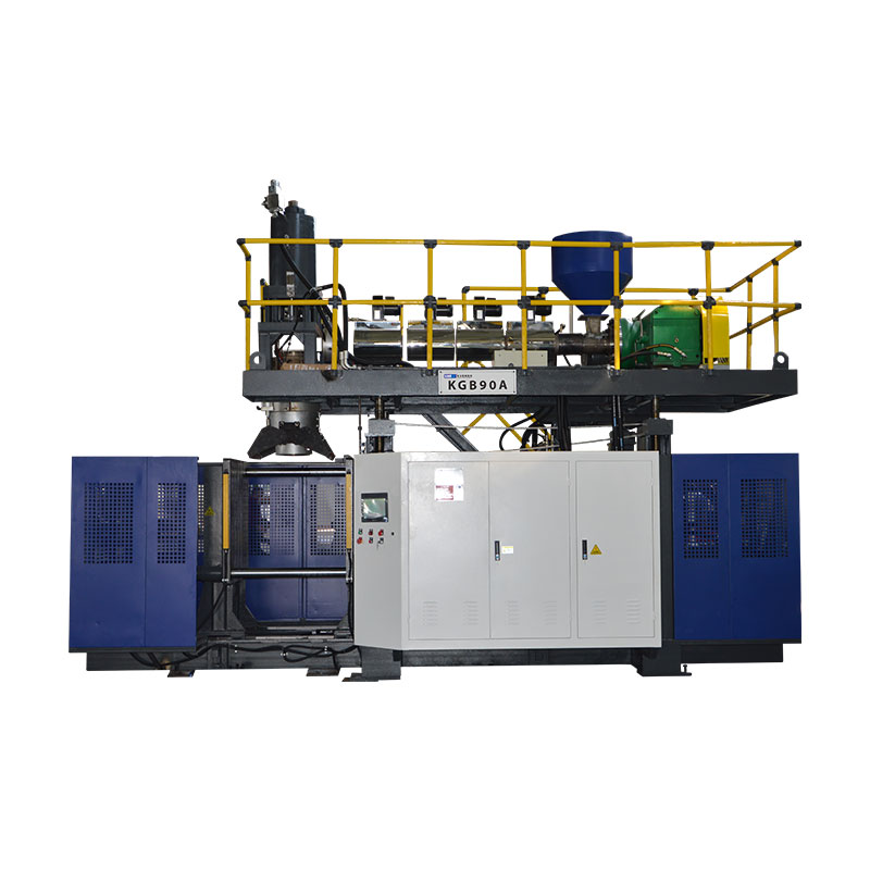
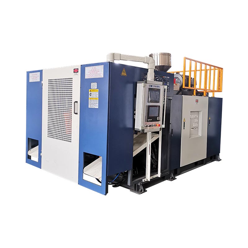
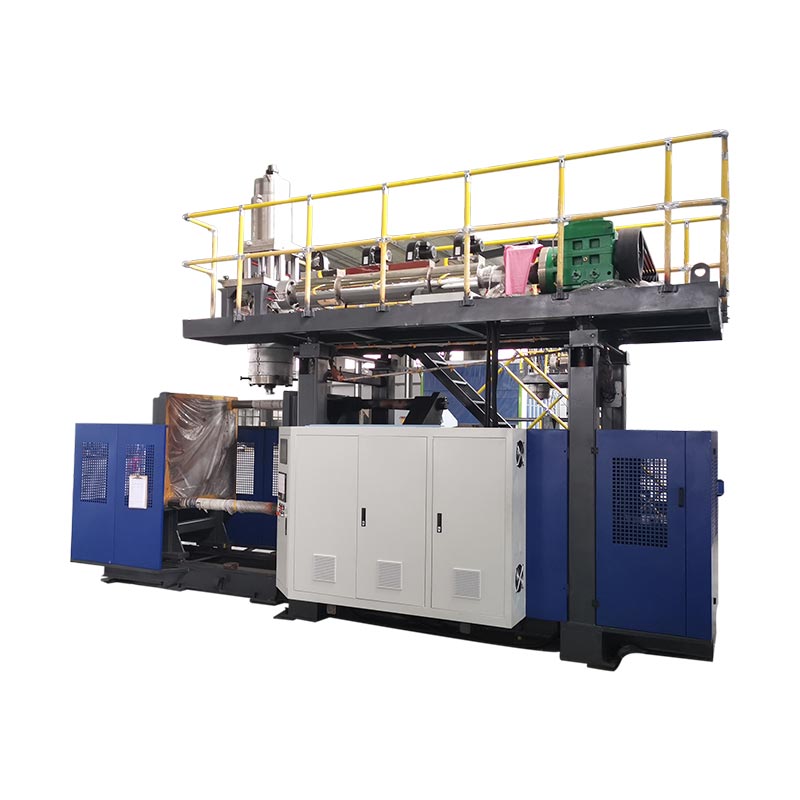
A machine can arrive on time and still miss its production date if the transformer, compressor, cooling system, foundation, lifting plan or service clearances are not ready. Utility planning should begin before the purchase order, not when installation starts.
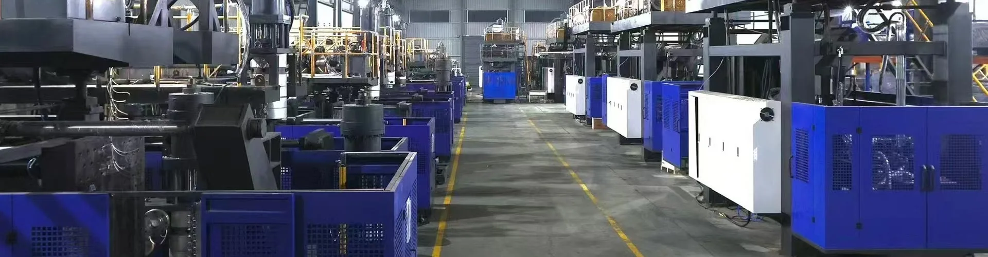
Published specifications are a starting point, not a plant design
Machine pages help buyers compare scale, but final utility demand changes with the selected extruder, die head, number of layers, hydraulic package, robot, mold, cooling circuit, leak tester, trimming, conveyor, grinder, material feeder and local electrical configuration.
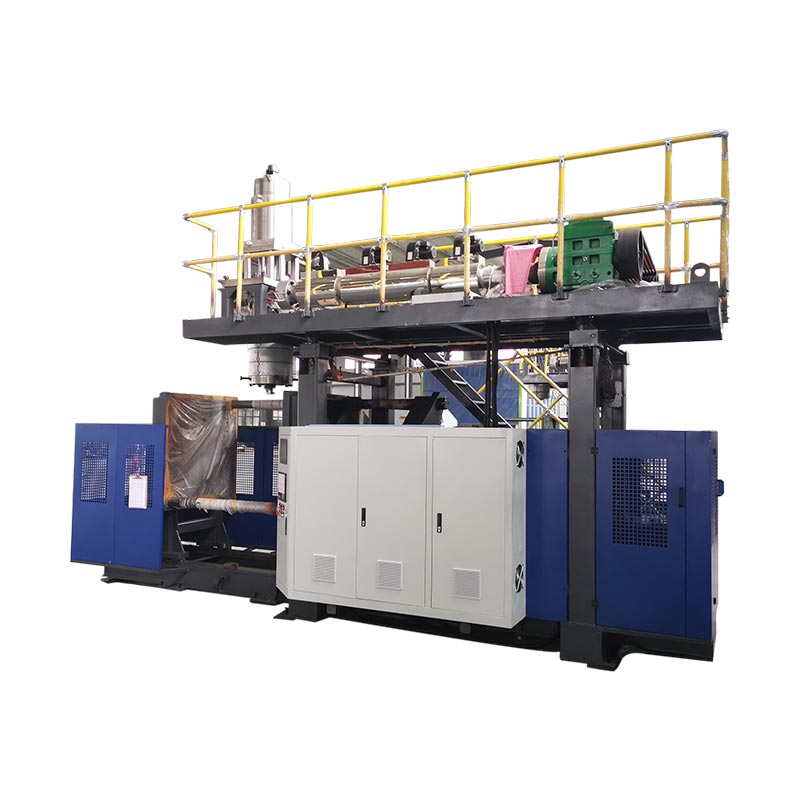
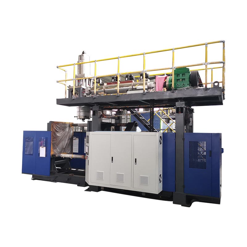
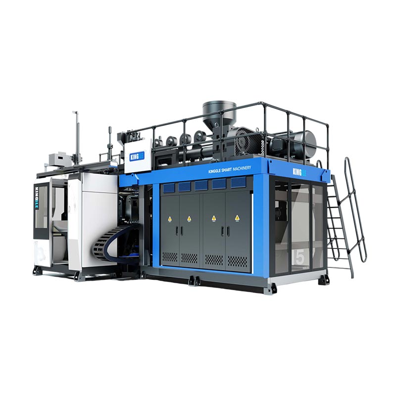
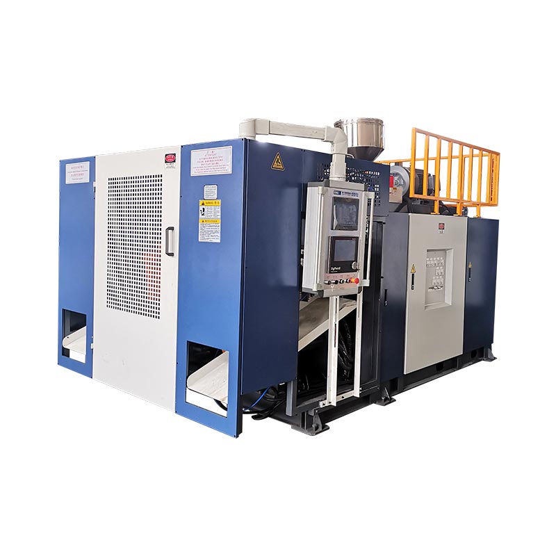
The following examples come from current Kinggle product pages. They show why a factory should size utilities around the actual configuration rather than a generic “blow molding machine” allowance.
| Published model example | Average energy consumption | Blow air | Cooling water |
|---|---|---|---|
| KGH30D 30 L double-station machine | 70–80 kW | 0.6 MPa; 1.8 m³/min | 0.2–0.3 MPa; 180 L/min |
| KGB90AP 60 L accumulator machine | 35–45 kW | 0.8 MPa; 1 m³/min | 0.3 MPa; 90 L/min |
| KGS1000L-IBC machine | 110–150 kW | 0.8 MPa; 2 m³/min | 0.3 MPa; 120 L/min |
Electrical power: separate connected load from operating demand
The installed load includes extruder motors, hydraulic pump motors, barrel and die heaters, cooling fans, control power, wall-thickness control, robots and installed auxiliaries. Not every load runs at full rating at the same moment, but the plant distribution system still has to support starting, heating and peak operating conditions.
Confirm with Kinggle
- Supply voltage, phase and frequency
- Total installed power and main disconnect rating
- Motor and heater loads
- Protective earth arrangement
- Cabinet cooling and environmental limits
- Requirements for voltage stability
Confirm inside the factory
- Transformer spare capacity
- Cable route and voltage drop
- Breaker coordination and local code
- Lockable isolation point
- Generator compatibility, if applicable
- Power for chillers, compressors and auxiliaries
Plan separate metering if you want reliable product-cost data. A whole-line meter gives a more useful result than estimating from nameplates because it includes compressor, chiller, grinder, conveyor and downstream loads.
Compressed air: pressure alone does not define capacity
Blow molding needs pressure and flow at the machine while other users in the plant are operating. A compressor may reach the required pressure at low demand but still allow pressure to collapse when several machines blow at once.
Map the complete path: compressor, aftercooler, dryer, receiver, main header, drops, filters, regulators, hose or pipe diameter, and the machine connection. Include pressure loss and simultaneous demand. Air quality also matters; water and oil carried into valves and product-air circuits can create maintenance and product problems.
Place a pressure gauge near the machine inlet. When a defect or alarm appears, the team can compare pressure at the machine with pressure in the compressor room instead of assuming the compressor set point reached the equipment.
Cooling water: specify temperature, flow, pressure and quality
A stated water flow does not tell you whether a cooling system can remove the heat. The engineering calculation also needs supply temperature, return temperature, ambient condition, water quality, mold circuit, oil cooler, feed-throat cooling and the heat load from auxiliary equipment.
Decide whether mold water, hydraulic-oil cooling and other circuits should be separated. Use manifolds and instruments that let maintenance isolate and check individual circuits. Provide strainers, water treatment and cleaning access appropriate to the local water source.
Unstable cooling can look like a machine or recipe problem: cycle time drifts, parts deform after ejection, dimensions change, oil temperature rises, and operators compensate with longer cooling. Record inlet and return temperature and pressure during acceptance so the factory has a baseline.
Factory layout: design for operation, maintenance and material flow
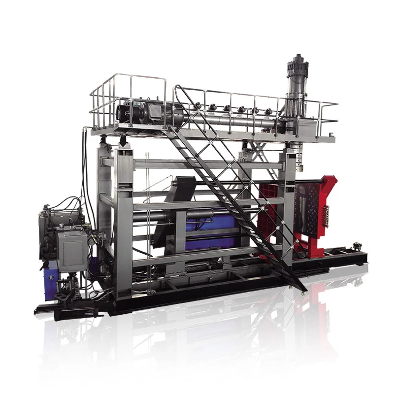
The general arrangement drawing should be placed inside a larger production-cell plan. Mark the machine, mold-change route, electrical cabinet doors, hydraulic service points, extruder removal path, die-head access, operator position, guarding, platforms, stairs and lifting zone.
Then add the material and product flow. Resin may pass through storage, conveying, drying or blending before it reaches the hopper. Finished parts may need deflashing, trimming, leak testing, weighing, labeling, inspection, packing and scrap return. Kinggle's application library shows how widely part size and handling needs can vary.
Keep forklift traffic away from control cabinets, hoses and operator stations. Provide an unobstructed path for molds, major components and emergency access. Check door width, roof or crane capacity, dock height and the transport path from unloading point to foundation before shipment.
Pre-installation checklist for the buyer and supplier
| Area | Information to freeze | Evidence before shipment |
|---|---|---|
| Machine configuration | Model, layers, die head, mold, robot and auxiliaries | Signed technical specification |
| Electrical | Voltage, frequency, installed load, main protection, connection point | Electrical drawing and cable schedule |
| Air | Pressure, peak flow, quality, pipe size and connection | Utility sheet and plant capacity check |
| Water | Flow, pressure, supply temperature, quality and circuit split | Cooling schematic and chiller/tower calculation |
| Civil work | Machine weight, load points, anchors, pit or drainage if required | Foundation drawing and structural approval |
| Space | Footprint, height, service clearances, mold change and lifting | Approved cell layout |
| Logistics | Crate dimensions, unloading method, doorway and route | Rigging plan |
| Acceptance | Product, material, mold, tests, utilities and output calculation | Agreed FAT/SAT protocol |
Use Kinggle's machine selection guide to define the part and output first. Utility planning becomes accurate only after the equipment configuration is matched to that job.
Frequently asked questions
Is average energy consumption the same as connected power?
No. Average energy consumption describes an operating estimate, while connected power includes the rated electrical loads that must be considered when designing the supply system.
Can I size the compressor from air pressure alone?
No. The compressor and distribution system must provide the required pressure and flow at the machine under simultaneous plant demand.
Does cooling-water flow alone define the chiller size?
No. Chiller selection also depends on supply and return temperature, heat load, ambient conditions, water quality, mold circuits and auxiliary equipment.
How much clearance should I leave around the machine?
Use the project general arrangement drawing and allow for cabinet doors, maintenance access, platforms, mold changes, component removal, lifting and safe operator movement.
When should utility planning begin?
Begin before the purchase order so the final machine configuration, factory infrastructure, delivery route and acceptance plan can be reviewed together.