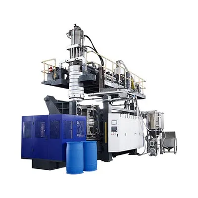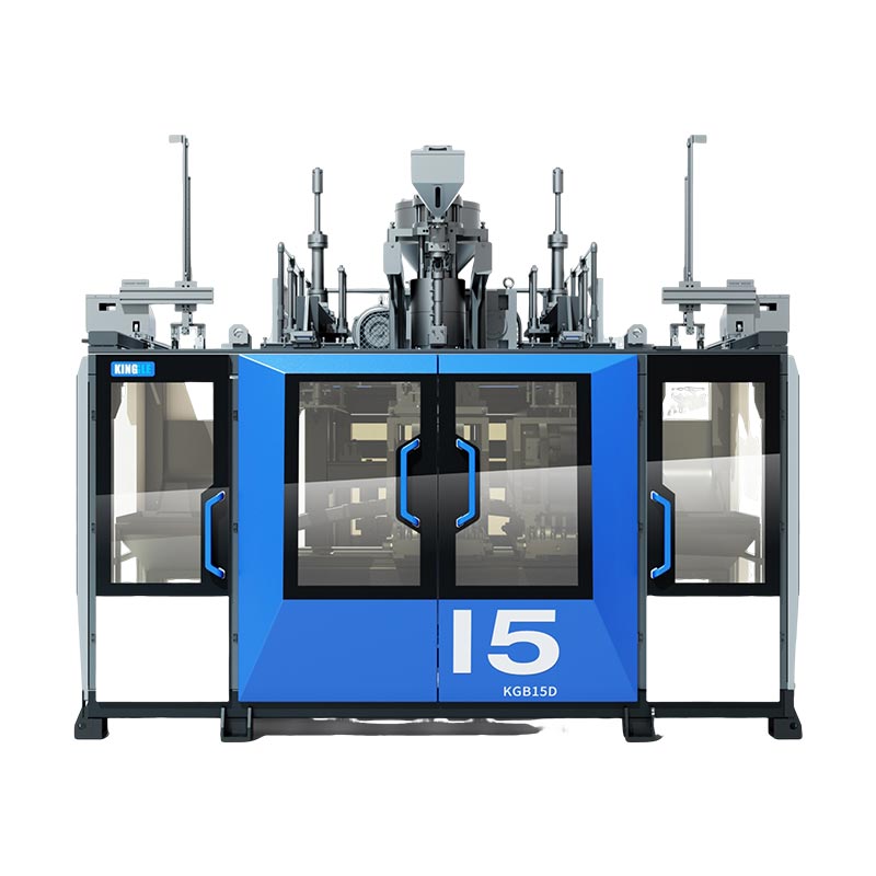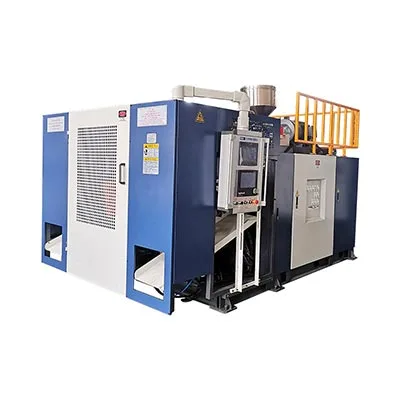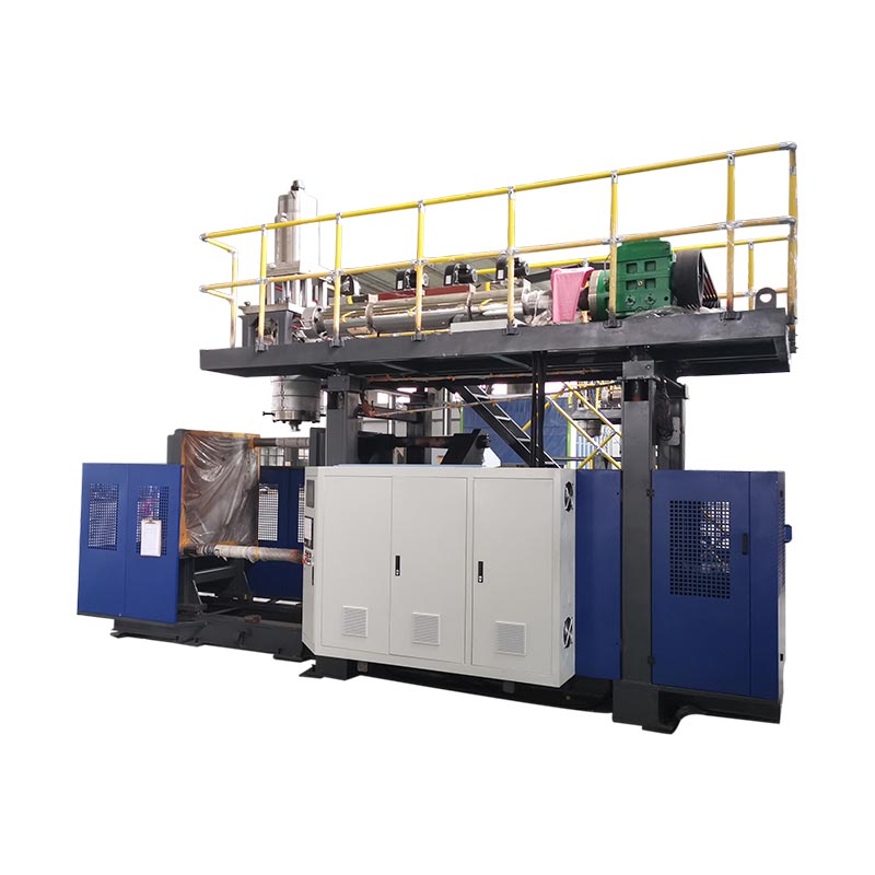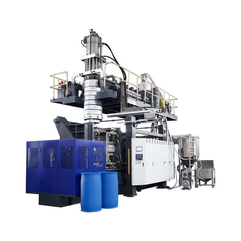
Blow molding shapes a hollow part by inflating hot plastic inside a mold. Thermoforming shapes heated plastic sheet. Single-sheet thermoforming is a candidate for open covers, trays and panels; twin sheet thermoforming also creates hollow structures, bringing it into direct comparison with extrusion blow molding.
For a large panel, duct or industrial hollow part, start with the drawing and required performance. Then compare the material, forming route, joints, finishing operations and cost per accepted part. A low mold quotation has little value if the proposed route cannot hold a mounting interface or withstand the specified load.
The equipment discussion here focuses on extrusion blow molding, or EBM. Injection blow molding and PET stretch blow molding need their own comparisons. SKZ's process overview provides the basic distinction between sheet forming and the inflation of a plasticized tube.

Blow molding vs thermoforming: key differences at a glance
Start with the part: open shell or hollow structure?
An open tray and a closed liquid container solve different problems. Comparing their unit prices does not identify the cheaper process for either product. The useful overlap is a part whose required function could be delivered by more than one route, possibly with a different design for each.
Compare single-sheet, twin-sheet and extrusion blow molding
| Review point | Single-sheet thermoforming | Twin-sheet thermoforming | Extrusion blow molding |
|---|---|---|---|
| Starting form | One heated sheet | Two heated sheets | An extruded molten tube, or parison |
| Basic structure | An open formed shell | Two formed sheets joined at designed contact regions | A hollow body shaped by internal air pressure |
| Tooling review | Draw, release, surface replication and trim | Both forming surfaces, alignment and joining regions | Parison capture, inflation, pinch-off, cooling and removal |
| Thickness review | Starting sheet and local stretching | Each sheet's distribution and joining regions | Parison distribution and local expansion |
| Finishing | Trim, openings and any assembly | Trim, openings and any additional assembly | Deflashing, openings and any additional assembly |
| Acceptance basis | Required dimensions, critical wall locations, functional performance and accepted output from the complete cell | ||
The table is a review framework. It does not establish a universal ranking for strength, tolerance, cycle time or tooling cost.
How does molding work? Blow molding and thermoforming explained
Where these processes fit among the types of plastic molding
Plastic molding methods differ in how they deliver and shape material. Ordinary injection molding fills a mold cavity with melt. EBM inflates a parison. Thermoforming reshapes sheet. These distinctions help narrow a project before equipment is quoted; listing every molding technique adds little once the viable routes are known.
The plastic blow molding process: from parison to hollow part
The extruder prepares the melt and the head delivers the parison. The mold closes around it, creates the required pinch-off regions, and holds the shape while compressed air expands the plastic against the cavity. Cooling, removal and finishing complete the cycle. Continuous extrusion and accumulator-head arrangements deliver material differently, so the proposed machine must suit the part's gross material requirement.
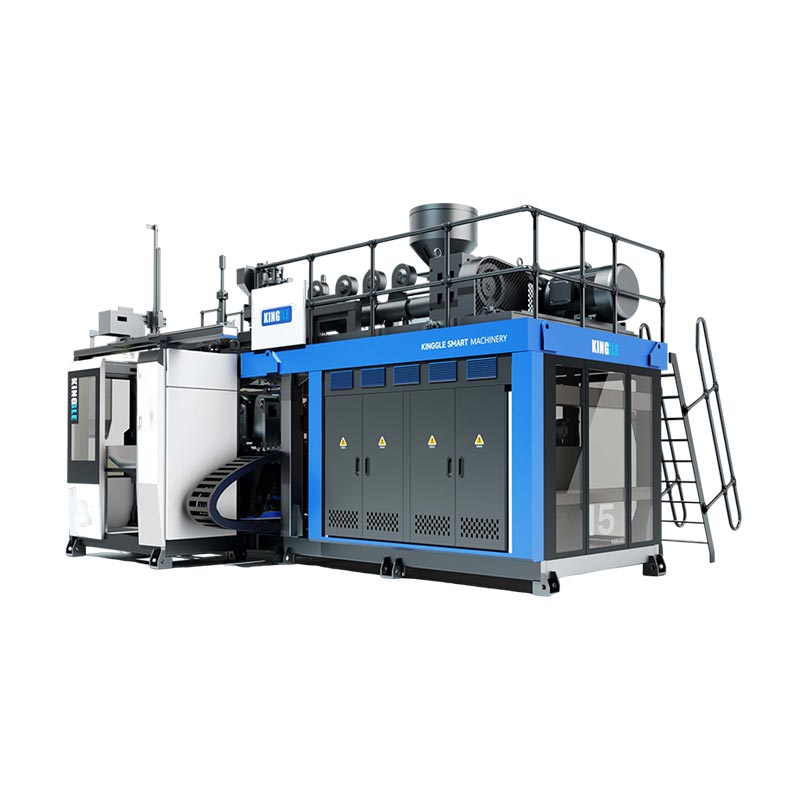
The mold defines the outside shape, while the material distributed through the parison affects the resulting walls. Check the extrusion head, mold, controls and resin as a working combination. Kinggle's machine parts and functions guide explains the equipment involved.
Single-sheet thermoforming: vacuum, pressure and forming aids
A sheet is heated, formed against tooling, cooled and trimmed. Vacuum, applied air pressure and suitable mechanical assistance are ways to shape it. They should not be confused with the separate distinction between single-sheet and twin-sheet construction. The forming sequence and tooling must account for local stretching and release.
Both processes require product-specific settings. SKZ identifies deformation, wall thickness and material behavior as linked process-development concerns. Free blowing of heated sheet for optical shapes is another use of pressure differences; it is not the same process as inflating an extruded parison.
Twin sheet thermoforming vs blow molding: which fits hollow parts?
What is twin sheet thermoforming?
Twin-sheet thermoforming forms two sheets and thermally joins them at designed contact areas to create a hollow or double-wall component. Joining belongs to the forming sequence; it should not automatically be costed as a separate adhesive or welding station. A 2025 original study on twin-sheet joints describes the combination of forming and welding within this process.
Match open shells, bottles, ducts and hollow panels to a process
For an open cover, investigate whether single-sheet forming already provides the function. For a necked container, examine the opening, closure and body requirements of the proposed blow-molded design. For a hollow panel, assess both twin-sheet and EBM designs where feasible. Part size alone does not settle that choice.
Keep the functional brief fixed while allowing the construction to change. The two routes may need different radii, contact regions, mounting details or finishing allowances. A direct substitution using identical nominal wall thickness and unchanged geometry can hide those differences.
Internal connections, inserts and functional features
Identify which features must be formed, which may be machined, and which require assembly. Review access for inserts, internal connections and fasteners with the tooling engineer. Neither route should be assumed capable of producing every internal feature in one operation. A hollow cavity also does not establish a sealed finished product: openings, joints and attachments still need evaluation.
Compare wall thickness, joints and finished-part performance
Minimum wall thickness matters more than average thickness
A finished part can meet its weight target and still have a thin critical corner. Specify the locations that matter: deep draws, corners, mounting interfaces, local connections and openings. For thermoforming, examine starting sheet thickness and how it redistributes. For EBM, examine the parison profile, sag and local expansion. Confirm the result on the actual proposed part.
Before adding material everywhere, investigate why the critical location is thin. A different distribution, geometry or forming condition may address the cause more directly. The revised part still needs functional testing; a thickness map alone does not prove stiffness or impact performance.
Pinch-off welds and twin-sheet fusion joints
EBM should not be described as having no weld regions. The mold closes on the parison to form a pinch-off weld. Research recorded by Penn State, published in 2004, examined how pinch-off geometry affects tensile load at that weld.
For twin-sheet parts, the 2025 joint study's public abstract identifies material, temperature, applied pressure and joining-plane geometry as relevant to joint quality. Neither study establishes that one process always produces the stronger finished structure. Locate the joints on the drawing and agree how their required function will be checked.
Measure dimensions, stiffness and sealing separately
Use material tests for the evidence they provide. ASTM D638-22 concerns tensile properties of standard plastic specimens under specified conditions. ASTM D790-25 addresses flexural properties using a three-point loading arrangement and suitable solid rectangular specimens. Neither is a blanket load rating for a hollow table panel or pallet.
ASTM also cautions that specimen preparation and test conditions affect results. Agree on finished-part checks for the actual support span, mounting system, load duration, environment and sealing function. A material data sheet cannot replace those checks, and a process name cannot establish an ingress-protection rating.
Choose a material grade for the process, not just a polymer name
Pellets and sheets have different purchasing requirements
For EBM, specify the resin grade and complete formulation supplied to the machine. For thermoforming, add the sheet construction, thickness specification and supply route. Sheet may be purchased or produced within a coordinated manufacturing operation. Its preparation cost and quality responsibility belong in the comparison either way.
Melt strength, formability and joining behavior
Two products described as HDPE do not automatically have interchangeable processing behavior. Review the grade's suitability for the proposed deformation and joining conditions. For a sheet-based route, verify sheet quality and formability; for EBM, verify parison formation and distribution. Use supplier technical information and trials with the actual formulation.
SKZ's material-development description emphasizes matching and monitoring rheological properties for these processes. That supports a grade-specific qualification, rather than a general temperature recipe for every polymer carrying the same name.
Validate the complete formulation and regrind plan
Include colorants, additives, layers and the intended reuse of trim. A change in any of these inputs may require renewed process or performance checks. Confirm food-contact, chemical-exposure or other use requirements separately where applicable. Successful forming does not provide that approval.
What equipment does each production route require?
Extrusion blow molding: match the mold, parison and cooling
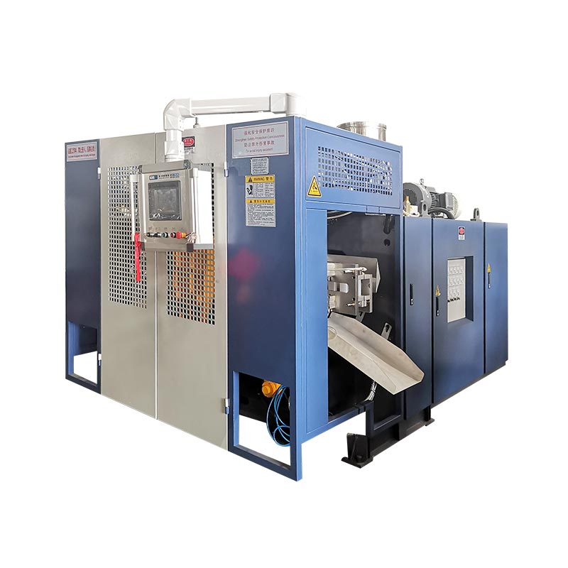
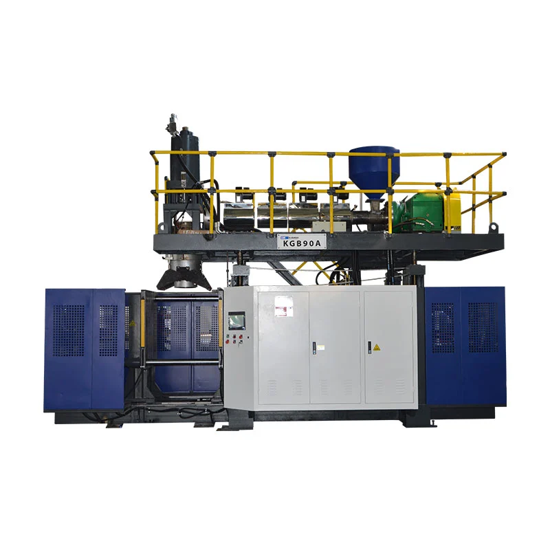
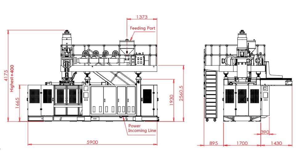
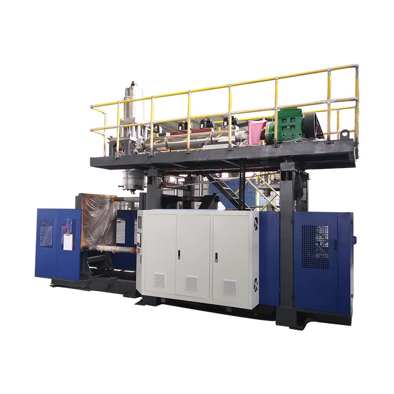
Begin with the mold envelope, mounting arrangement and removal path. Then review plasticizing, usable material delivery, parison control, cooling and finishing. For a wide, shallow panel, the available mold space may be a more useful initial filter than the machine's nominal container capacity.

That page lists a 1,300 × 1,900 mm mold platen and an HDPE plasticizing figure of 350 kg/h. These are catalogue fields with different purposes: one describes installation space, the other a material-processing capability. Neither establishes the accepted output of a particular tabletop. Confirm the mold envelope, mounting and operating conditions with the supplier.
The same table labels 300 pieces/hour as a dry-cycle figure. It must not be treated as 300 finished, cooled, trimmed and inspected products per hour.
Thermoforming: include sheet supply, heating, forming and trimming
Specify who supplies the sheet and how its quality is controlled. Review the heating arrangement, forming area, mold release, cooling and trim operation. For twin-sheet work, add tooling alignment and the joining requirements. Establish which operations run together and which need a separate station or operator.
Compare the whole cell, not two machine nameplates
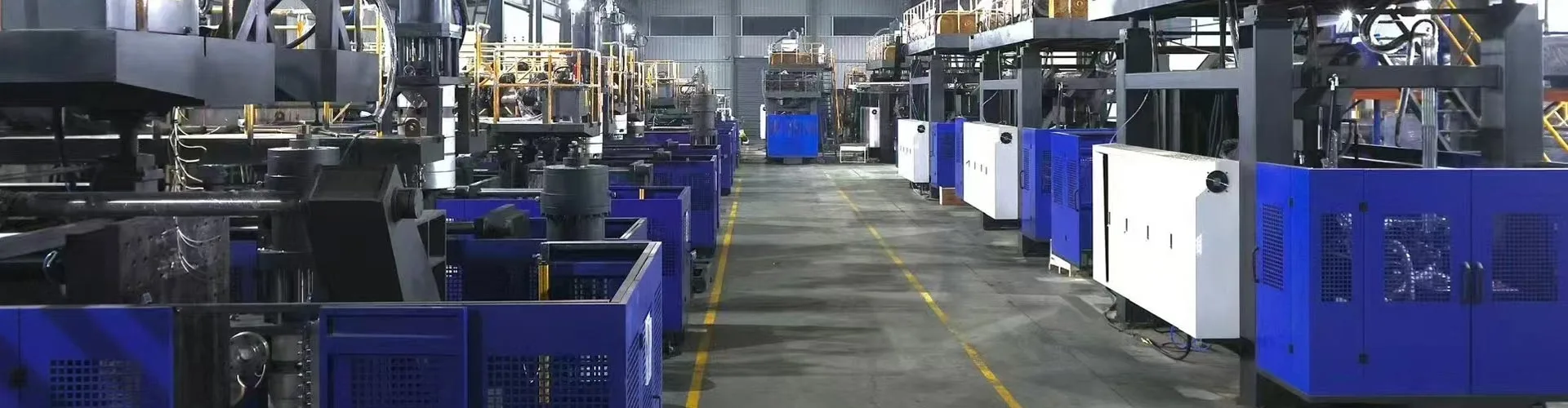
Map all operations from incoming material to accepted part. Record utilities, floor space, staffing, handling, scrap processing and inspection. A faster forming cycle will not increase cell output if trimming or cooling remains the bottleneck. Quote the cell against an agreed product and operating schedule.
Which process costs less per accepted part?
Separate tooling, equipment and running costs
Use the same accounting period and accepted-part quantity for both routes. Include the fixed cost allocated to that period and the variable cost of delivering an accepted part. If equipment ownership is already included in the fixed allocation, do not add the same depreciation again.
Compare quotations with matching scope: tooling, auxiliaries, installation, finishing and inspection. Keep finance and residual-value assumptions consistent. A tooling-only comparison answers a narrower question than the cost of establishing production.
Count trim, reuse and rejected parts correctly
Gross material processed is not the same as newly purchased resin. Reused trim may circulate through the process again, consuming capacity and handling effort without becoming a second purchase of virgin material. Identify permitted reuse, unavoidable losses, rejected parts and any cost of returning material to production.
Calculate the break-even volume from your own inputs
Consider a hypothetical hollow-panel project. I would first hold the functional requirements and cost boundary constant. For this calculation, assume both routes meet acceptance requirements and the required output. Over the same accounting period, the EBM route has CNY 120,000 more allocated fixed cost, but its variable cost is CNY 8 lower per accepted part. These are illustrative inputs, not equipment quotations or trial results.
| Accepted quantity | EBM variable-cost saving | Additional EBM fixed allocation | Total cost difference |
|---|---|---|---|
| 12,000 parts | CNY 96,000 | CNY 120,000 | EBM costs CNY 24,000 more |
| 15,000 parts | CNY 120,000 | CNY 120,000 | Equal calculated cost |
| 30,000 parts | CNY 240,000 | CNY 120,000 | EBM costs CNY 120,000 less |
Cost difference = CNY 120,000 − (CNY 8/accepted part × accepted quantity)
The calculated crossing point is 15,000 accepted parts. I would use it only within those assumptions. It is not a general industry threshold. If higher demand requires another shift, more equipment or a different formulation, update the fixed and variable costs and check capacity again.
Process qualification comes first. SKZ describes developing parameters for each material and product; it does not provide the cost figures above. Insert the project's own quotation and operating data before using this calculation for investment planning.
Process selection by application
Packaging: bottles and containers versus open trays
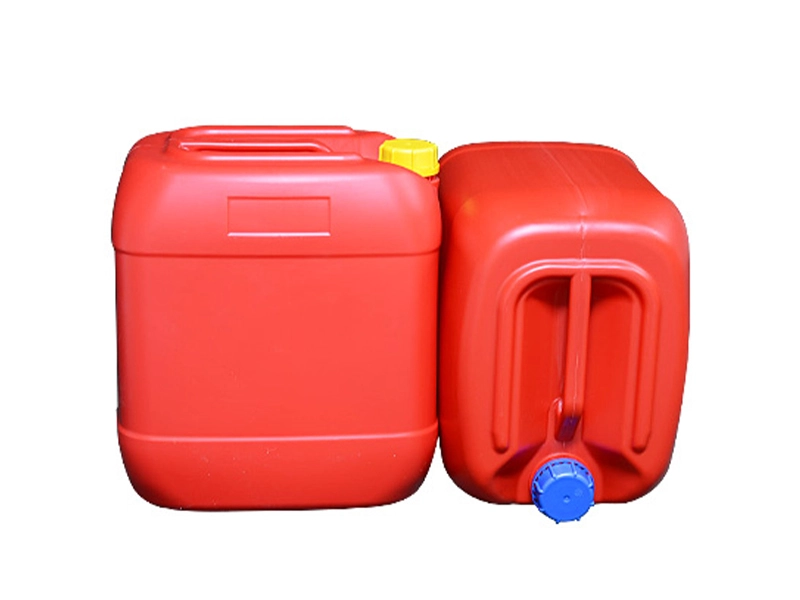
A necked hollow package and an open tray have different structural tasks. Begin by deciding which geometry the package actually requires. If a different container design is proposed, compare closure, filling, handling and use requirements before comparing manufacturing cost.
Industrial parts: table panels, pallets and protective structures
A hollow table panel is a useful comparison task because the top surface, lower structure and frame attachments must work together. Twin-sheet and EBM proposals can be reviewed against the same mounting and performance brief, while allowing the design changes each route needs.
| Product task | Initial route review | Evidence to request |
|---|---|---|
| Open cover or tray | Assess single-sheet forming first where the function allows it | Formed geometry, trim, interfaces and appearance |
| Hollow tabletop or equipment panel | Compare viable twin-sheet and EBM constructions | Wall map, joining regions, mounts and supported performance |
| Pallet or handling structure | Assess the proposed construction and handling conditions | Support, payload distribution, fork access and relevant product tests |
| Duct or hollow fluid component | Review the path, openings, material and manufacturing access | Interface dimensions, joints and the specified flow or sealing function |
Kinggle's KGS135A pallet machine is a separate equipment entry for pallet projects. Its application label does not establish that a particular pallet meets its handling requirements.
Ducts and equipment components
Review bends, connections, access, installation clearances and service conditions. A process can produce a hollow body yet still need secondary work to provide the required interfaces. Include that work in the drawings, acceptance plan and cost comparison.
Which plastic molding method fits your project?
Fix the product requirements first
When evaluating blow molding and thermoforming, I would first mark the drawing: which regions carry load, which dimensions locate an assembly, and where sealing matters. Similar appearance and weight are not enough to make the routes interchangeable.
For a large hollow panel, I would examine the EBM pinch-off region and the twin-sheet fusion regions, then check minimum wall thickness near corners and mounting holes. If a local wall is too thin, I would investigate material distribution, heating or parison control before adding weight across the whole part.
I would also put cooling, removal, trimming and inspection into the same process map as the main machine. At trial review, dimensions, wall thickness, joint quality and functional checks need separate records. The final comparison is the cost of consistently delivering accepted parts from that complete cell. This sequence helps identify structural problems before they become production problems.
Eliminate infeasible routes before comparing prices
Ask the supplier to resolve the features that could rule out a route. If the proposed construction cannot meet an essential interface or use requirement, a detailed operating-cost estimate is premature. Where a change would make the route feasible, obtain design approval before requesting a firm comparison.
Compare remaining routes on the same basis
| Requirement | Evidence | Next action if unresolved |
|---|---|---|
| Geometry and interfaces | Process-specific design and tooling review | Revise the feature or exclude the route |
| Material and joining | Grade information and representative trials | Qualify the complete formulation |
| Finished-part function | Agreed tests under relevant use conditions | Resolve the failing region and retest |
| Output and cost | Complete-cell proposal on an accepted-part basis | Check the bottleneck and update the calculation |
What to send a supplier, and what to verify in a trial
Prepare a useful RFQ package
Send the drawing or 3D model, material and formulation, key interfaces, required performance and design-change limits. Add accepted output, operating schedule, available utilities, floor space and the intended finishing and inspection scope. Mark features that must remain fixed and those open to a process-specific redesign.
Agree on product and cell acceptance
Specify where walls and dimensions will be measured, what constitutes an acceptable joining region, and which functional tests apply. Agree on conditioning, sample selection and the production period used to assess output. Record material and machine conditions so the evidence can be tied to the actual proposal.
Keep the stages distinct: dimensional approval, functional approval and production-cell acceptance answer different questions. A good-looking first sample does not settle all three.
Match an extrusion blow molding machine to the approved part
Once EBM is a viable route, the KGS120Z table and panel machine provides a starting point for discussing a large panel project with Kinggle. Send the product requirements to sales@kinggle.com for a configuration review. The useful next step is a proposal matched to the mold, material, finishing operations and acceptance brief.
Frequently asked questions
What is the main difference between blow molding and thermoforming?
Blow molding inflates hot plastic inside a mold to create a hollow part. Thermoforming shapes heated sheet. Single-sheet forming produces an open shell; twin-sheet forming joins two formed sheets to create a hollow or double-wall structure.
When is twin sheet thermoforming an alternative to blow molding?
It is worth evaluating when a hollow or double-wall part can be designed around two formed sheets and their joining regions. Compare it with a viable blow-molded construction against the same interfaces, performance, output and cost boundary. Hollow geometry alone does not make the routes interchangeable.
Is vacuum forming the same as thermoforming?
Vacuum forming is one way to thermoform sheet. Thermoforming also includes processes that use applied air pressure or mechanical assistance. Single-sheet and twin-sheet describe the sheet construction and forming arrangement, rather than an identical classification by forming force.
Is twin-sheet thermoforming cheaper than blow molding?
Neither route is always cheaper. Compare tooling, equipment allocation, material supply, trim and reuse, staffing, utilities, finishing and rejected parts over the same period and accepted quantity. A break-even calculation is useful only while its cost and capacity assumptions remain valid.
Which process gives more uniform wall thickness?
The process name does not guarantee the required thickness distribution. Thermoforming depends on the starting sheet and local stretching; extrusion blow molding depends on parison distribution and expansion. Check minimum thickness at defined locations on the proposed part, then verify the relevant function.
Can blow molding make large panels and double-wall parts?
Extrusion blow molding can be considered for suitably designed hollow panels, including structures with separated opposing walls. Review the proposed connections, mounting features, mold space, material delivery and cooling. The label double-wall is not a complete specification or proof of functional performance.
Can the same plastic grade be used for both processes?
Do not assume interchangeability from the polymer name. Confirm the exact grade, formulation, sheet or parison requirements, and joining behavior for each route. Qualification must cover the resulting part and its intended conditions of use.