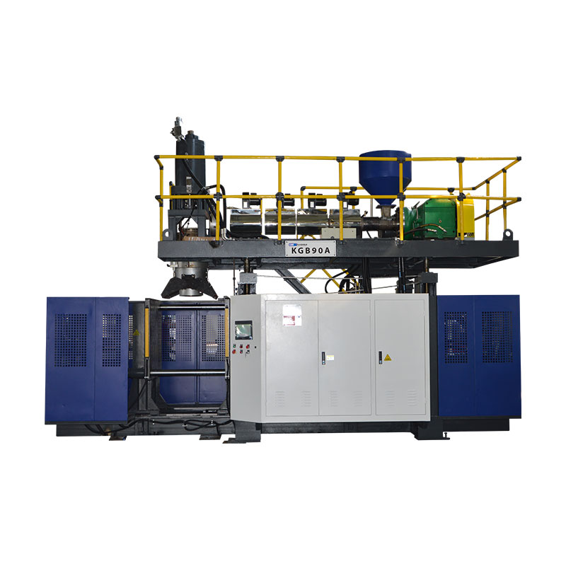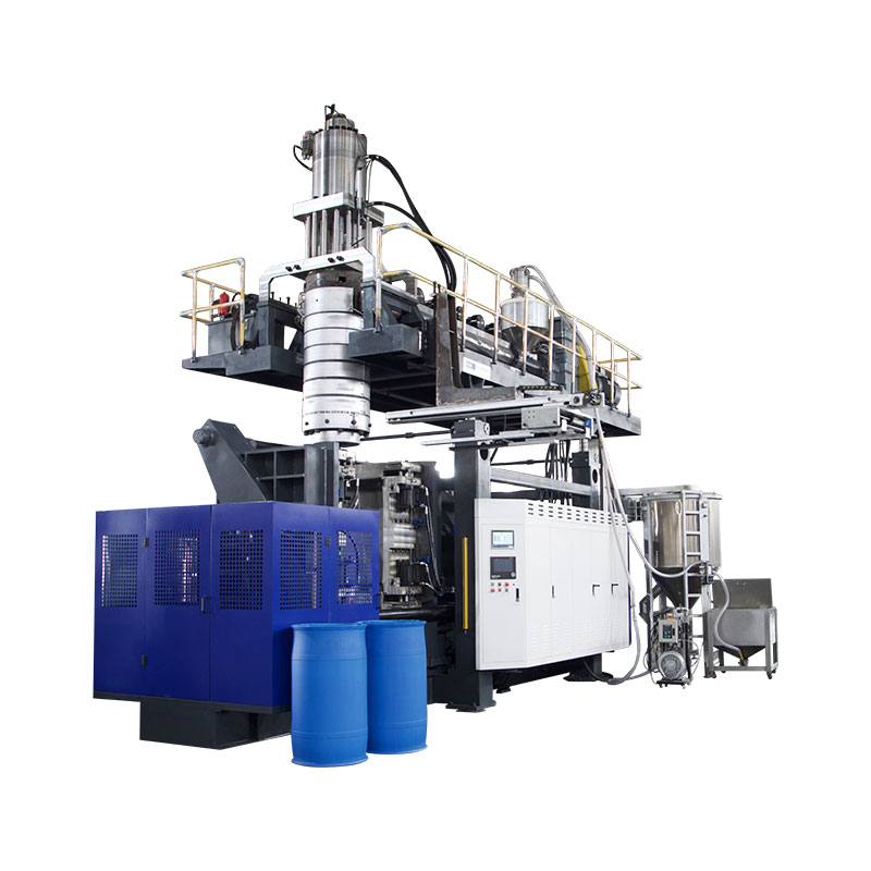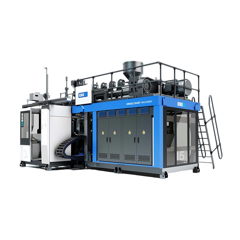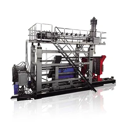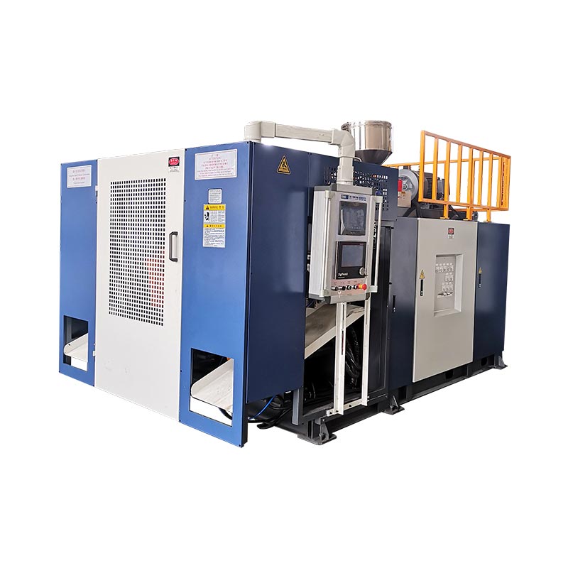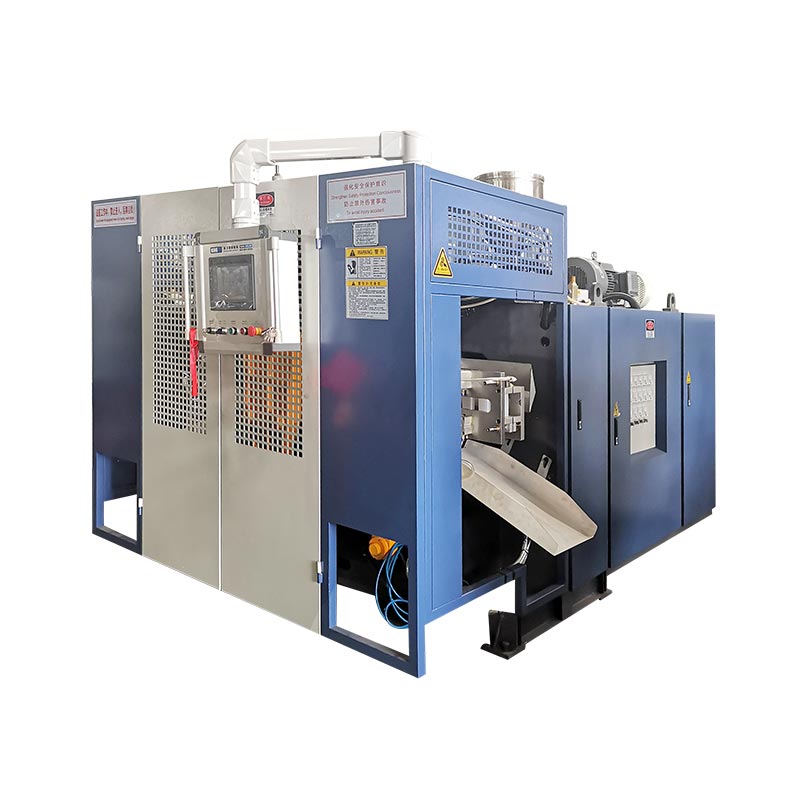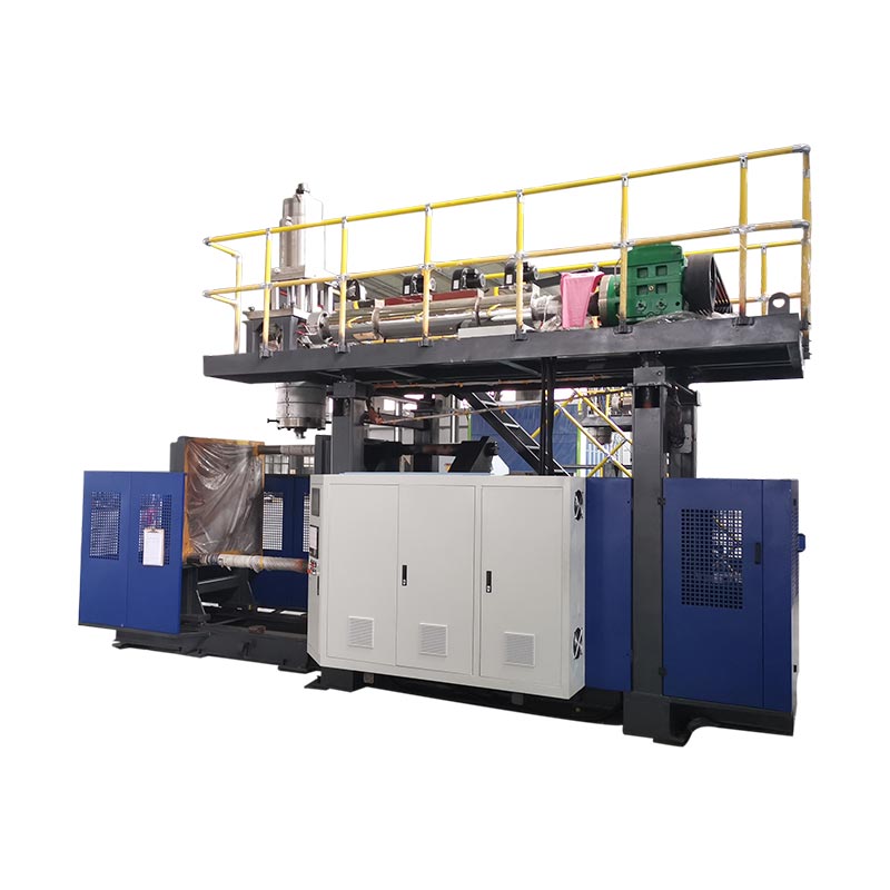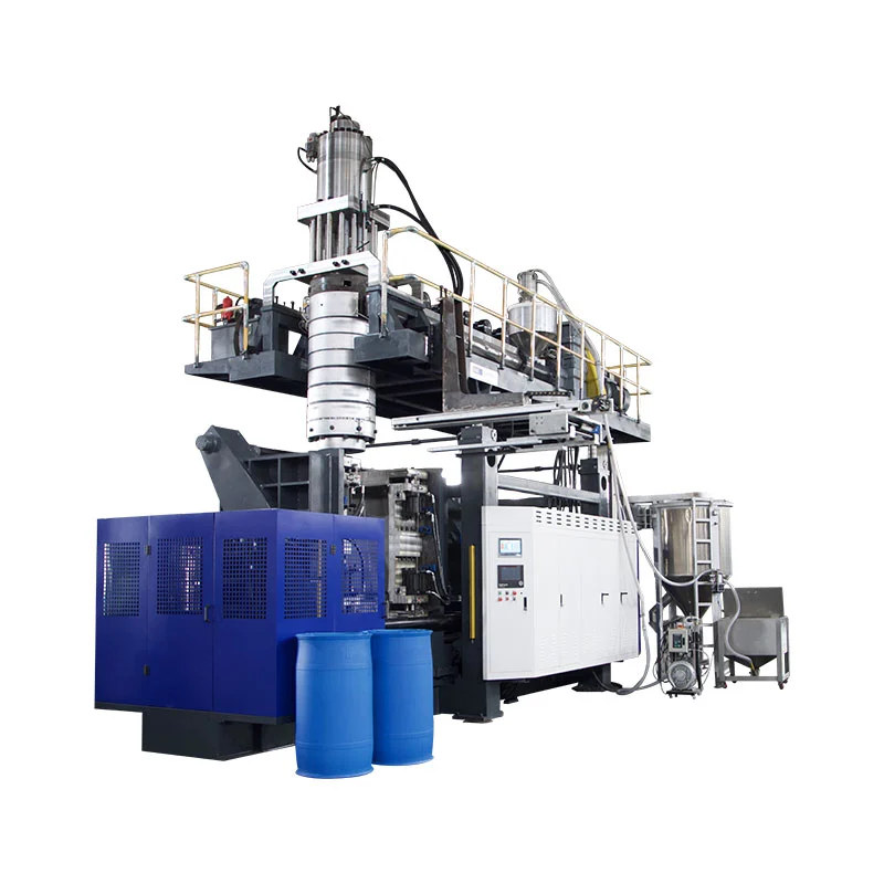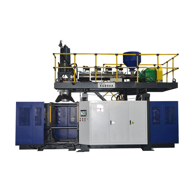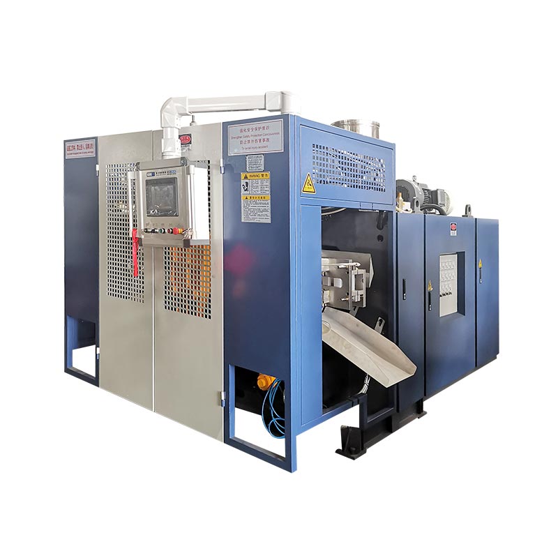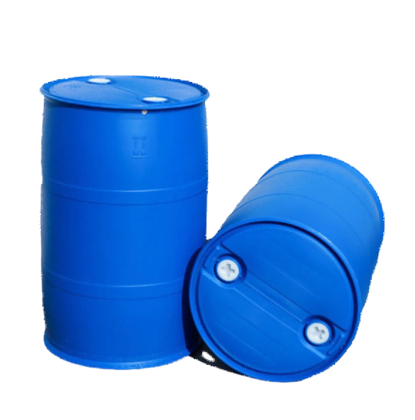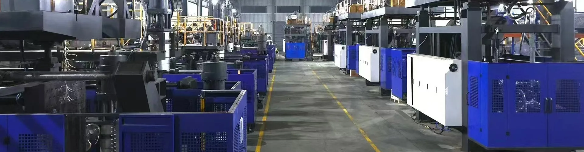
The KGB100B is a candidate for large hollow products only when the part, mold, gross parison and factory all fit its published limits. Kinggle lists a 120 L maximum container capacity, a 920 x 1200 mm maximum mold size, a 12(20) L accumulator reference and a 9(15) kg PE accumulator-weight reference. Those figures start the engineering review, but a product drawing and trial plan must settle the final choice.
A buyer searching for a 120L blow molding machine usually has a real part in mind. It may be a chemical drum, traffic barrier, float, tank, toy or large technical component. The volume label is useful, but it does not describe the hardest areas, mold movement, wall distribution or cooling demand.
This guide reads the KGB100B as a production system. It explains what each published number can tell you and what it cannot. It also shows what to send with an RFQ, so the discussion can move from a general machine name to a testable solution.
Six questions for a fast product-fit check
- Does the complete mold fit the platen, mold envelope and thickness range?
- Can the cooled part leave the mold through the available opening?
- Is gross parison mass within the selected accumulator configuration?
- Can the extruder recover enough material for the target cycle?
- Can clamp force contain the agreed projected area and blow pressure?
- Can the plant supply stable power, cooling water and compressed air?
Specification boundary: the figures in this guide come from the current Kinggle KGB100B product page. They were checked on September 15, 2026. Treat them as published screening references. The approved quotation, layout, machine drawing and technical agreement must define the ordered machine.
A 120L label is a starting point, not product approval
Kinggle publishes 120 L as the KGB100B maximum container capacity. That gives buyers a quick range marker. It does not say that every part below 120 L will run on the machine. A compact drum and a long traffic barrier can have very different mold widths, projected areas, parison lengths and removal paths.
Nominal volume can also hide material demand. A large thin-walled float may contain more air but less resin than a smaller technical part with thick ribs, handles and pinch zones. The machine must form the complete hot parison, including material that later becomes flash or trim. Finished product weight alone therefore understates the shot that the head must deliver.
Geometry changes the decision again. Deep draw areas can stretch the parison heavily. Wide panels may need more clamp force. Long parts can be limited by die-to-mold distance or take-out space before container volume becomes relevant. Neck inserts, internal threads and bottom blowing can add more movement to the cycle.
Use the 120L description to build a shortlist. Then compare the real part and mold with the machine. This is why Kinggle's own sales process asks for product photos, drawings, weight, size, material, thickness and output requirements before a model recommendation.
That sequence keeps the capacity label in its proper role: quick screening first, engineering confirmation second.
Turn the KGB100B specification into buyer questions
A specification table is most useful when every number leads to a check. The KGB100B page covers machine size, clamping, extrusion, the accumulator head and utility references. Some values are clear limits. Others describe a published configuration or a no-load machine condition.
The page lists the accumulator as 12(20) L and the PE accumulator weight as 9(15) kg. The parentheses appear to indicate listed alternatives, but the page does not define the selection rule. The quotation should therefore name one head arrangement and its material scope. Do not combine the larger figure with a standard machine assumption unless Kinggle confirms it for the project.
| Published field | KGB100B reference | Question it should trigger |
|---|---|---|
| Maximum container capacity | 120 L | Does the actual product geometry and gross parison fit, not only its nominal volume? |
| Output | 320 pcs/h, dry cycle | What output can the machine hold with the production mold, resin, cooling and quality rules? |
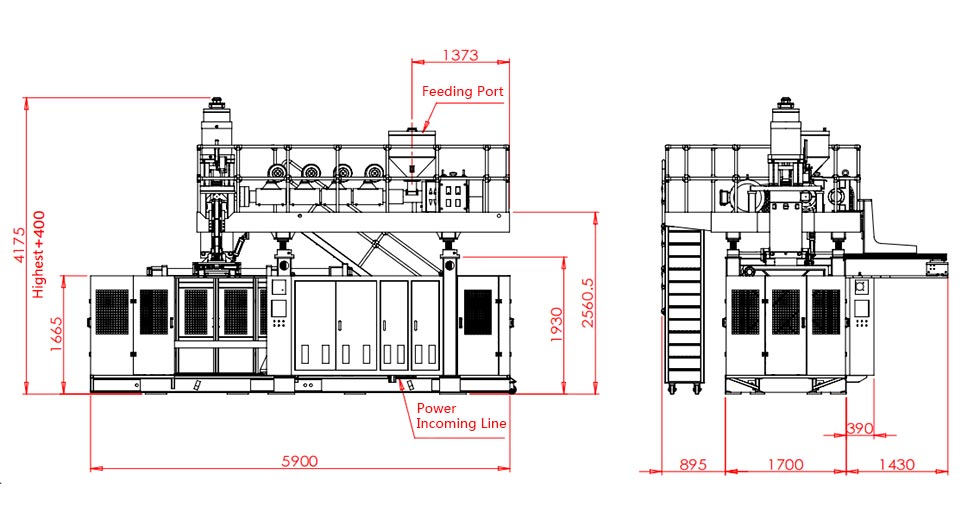
| Machine size | 5.9 x 3.8 x 4.6 m | Is there enough installed space for access, platforms, hoses, handling and maintenance? |
| Machine weight | 18 t | What foundation and rigging plan follows the final general arrangement drawing? |
| Clamping force | 440 kN | Is it sufficient for the product's projected area at the agreed process pressure? |
| Platen and mold references | 1200 x 1200 mm platen; 920 x 1200 mm maximum mold | Do the mold body, mounting pattern, services and connections fit together? |
| Opening and movement | 500 to 1400 mm opening; 600 mm moving stroke | Can the part release and exit without collision or damaging hot surfaces? |
| Mold thickness | 510 to 600 mm | Does installed thickness include backing plates, adapters and required tooling? |
| Extruder | 100 mm screw; 24 L/D; 55 kW motor | Does the selected screw and process window suit the stated resin? |
| Published HDPE melting capacity | 160 to 200 kg/h | Is gross material demand below a proven stable output for the actual formulation? |
| Accumulator head | 12(20) L; 9(15) kg PE reference | Which option is quoted, and does it cover gross parison mass with a usable process margin? |
| Die-pin diameter | Maximum 450 mm | What die and tooling package is needed for the parison diameter and product layout? |
| Cooling-water reference | 0.3 MPa; 120 L/min | At what inlet temperature, water quality and circuit scope does this apply? |
| Published average energy line | 52 to 60 kW | What product-related kWh/kg and kWh per accepted part are measured during a stable trial? |
The product page also publishes 0.8 MPa blow pressure and an air-flow figure of 1.8, but its visible unit is rendered as M2/MIN. That unit needs correction or confirmation before it enters a facility specification. A responsible RFQ should flag the uncertainty instead of silently changing the unit.
Read related rows together. Mold size belongs with opening and thickness. Accumulator mass belongs with the selected resin and gross shot. Melting capacity belongs with recovery time and stable melt quality. Machine dimensions belong with maintenance access and auxiliary equipment. This connected reading prevents one favorable number from hiding a different project constraint.
Check the mold envelope and the part removal path
The published maximum mold size is 920 x 1200 mm. The platen is 1200 x 1200 mm, and the mold thickness range is 510 to 600 mm. These values describe related dimensions, but they are not interchangeable. A mold may fit the stated face dimensions and still conflict with tie rods, pipes, mounting holes or moving equipment.
Begin with an assembly drawing, not a product sketch. Show both mold halves, backing plates, water manifolds, blow pins, neck or bottom tooling, hydraulic devices, sensors and electrical boxes. Identify the centerline and mounting pattern. Mark every item that moves outside the mold body during opening.
Next, simulate removal. The KGB100B page publishes a 500 to 1400 mm platen opening reference and a 600 mm platen moving stroke. The finished part needs clear space to release, rotate if necessary and leave the machine. Flash, tails, handles and hot flexible walls can enlarge the real removal envelope.
Part stiffness also matters. A large hollow part may deform if a robot grips it before the wall is ready. A simple drop can damage a neck or leave a mark on a warm panel. Cooling time inside the mold and support after ejection belong in the layout review.
Factory view: keep the mold drawing beside the machine general arrangement. Add the crane hook path, mold-cart route, service-side clearance and the operator's safe access. The published 5.9 x 3.8 x 4.6 m machine dimensions are not the complete cell footprint.
A proper review also includes mold weight and lifting points, even though the public product page does not publish a mold-weight limit. Ask Kinggle to confirm allowable mold weight and the recommended handling method for the exact configuration. The extrusion blow molding mold design guide provides a fuller checklist for cooling, pinch-off and venting.
Size the accumulator from gross parison mass
An accumulator head stores melt and pushes out a large parison on demand. The relevant material quantity is the complete shot leaving the head. It includes the saleable part, top and bottom flash, handle or neck scrap, and any other trimmed material created by the selected tooling.
Gross parison mass = finished part mass + flash and trim mass + controlled process allowance
The allowance is not a universal percentage. It should come from the approved part, mold concept, material behavior and trial result.
Kinggle publishes 9(15) kg as the PE accumulator-weight reference for the KGB100B. That is not a promise that the finished product can weigh 9 or 15 kg. It is also not automatically transferable to PP, ABS or a filled formulation. Resin density, melt strength, temperature and head condition affect the usable process window.
The 12(20) L accumulator capacity line needs the same care. Liter capacity describes volume inside the system, while the product drawing and material plan are usually managed by mass. Ask which head option is included, which resin supports the published mass, and how much material remains in the head at the agreed operating point.
Do not run at a theoretical limit by default. A project needs enough control range to correct wall distribution and shot-to-shot variation. If the gross parison occupies nearly all available capacity, a later material change or local thickness correction may remove that room. The trial should show stable shot mass, repeatable parison length and acceptable cushion for the selected head.
For a multi-part mold, count every parison released per cycle. The complete shot must cover every active outlet and its trim. Head count and cavity count can change the math, so state them separately in the RFQ. The head and cavity guide explains that distinction.
Match the extruder to material demand and recovery time
The KGB100B page lists a 100 mm screw, 24 L/D ratio, 55 kW extruder motor and four heating zones. It publishes an HDPE melting-capacity range of 160 to 200 kg/h. That range is a material-scoped reference. It should not be treated as a guaranteed output for every grade, masterbatch, regrind ratio or temperature window.
Convert the production target into gross hourly demand. Use gross parison mass, not finished part mass. Include all active positions and use the planned events per hour. This gives the material rate that the extruder and head must sustain while the machine is making acceptable parts.
Gross material demand, kg/h = gross parison mass per event, kg x molding events per hour x active parisons per event
Compare the result with a trial on the actual formulation. A brochure range alone cannot establish melt quality or recovery margin.
Recovery time must fit inside the machine cycle. If the mold stays closed for cooling, the extruder often uses that time to recharge the accumulator. A shorter cooling cycle can therefore raise the required melt rate. Faster mold motion has little value if the head is not ready for the next shot.
Material handling can become the hidden constraint. Large parts consume resin quickly. The plant needs reliable conveying, drying when the material requires it, blending and contamination control. Regrind can change bulk density and feed behavior. A written formulation is more useful than a broad label such as “HDPE plus regrind.”
Ask the trial record to include resin grade, supplier, color package, regrind percentage, temperature settings, screw speed and actual gross mass. If another material is planned, request material-specific evidence. Kinggle's HDPE and PP processing guide explains why the polymer label alone does not settle the machine setup.
Connect clamp force, projected area and blow conditions
The KGB100B page publishes 440 kN of clamping force. A larger number is not automatically better, and a volume label cannot validate the clamp. The mold sees separating force across the projected area exposed to internal pressure. Product shape, flash land, pinch-off design and process pressure all influence the real requirement.
Projected area is the silhouette of the pressurized cavity on the mold parting plane. A broad flat component can create more separating load than a deeper but narrower container. The review should use the actual cavity drawing. It should also include the selected blow pressure and any agreed safety factor.
The public page lists 0.8 MPa as the blow-pressure reference. That does not mean every product should run at the same setting. Resin temperature, venting, wall thickness, surface detail and cooling strategy affect the process. The factory trial should use a documented production window that produces acceptable parts without flash growth or unstable mold behavior.
Pinch-off design is part of the same system. Weak sealing can create leakage or a fragile weld. Excessive material can enlarge flash and make trimming harder. Mold alignment, clamp motion and parison placement must support the tooling rather than compensate for it.
Ask the mold supplier and machine supplier to review the same drawing. This prevents a common gap where each party approves only its own equipment. The final technical agreement should name projected area, process pressure, clamp requirement, mold thickness, mounting and connection details.
Plan the factory around the complete molding cell
The KGB100B page publishes a machine size of 5.9 x 3.8 x 4.6 m and a weight of 18 t. These are valuable starting points for layout and rigging. They do not include every platform, resin system, chiller, compressor, take-out device, conveyor, trimmer or safety boundary.
Start above the machine. Confirm clear building height, crane capacity, head-removal path and access to heaters and hydraulic components. Then work outward. Operators need space to inspect the mold, remove a stuck part and reach normal service points. Material delivery and finished-part handling need routes that do not cross unsafe zones.
Cooling water deserves more than a pipe-size estimate. The page lists 0.3 MPa and 120 L/min, but the plant also needs the required inlet temperature, acceptable temperature rise, water quality, filtration and return condition. Mold circuits and oil cooling may need separate control. The final utility sheet should state what is included in the published flow.
Compressed air needs the same treatment. The website gives a 0.8 MPa pressure reference, yet its visible air-flow unit is inconsistent. Request a corrected machine-inlet demand, peak demand, air quality, dew point and connection size. A receiver may be needed to keep pressure stable during large blowing events.
The product page labels 52 to 60 kW as “average energy consumption.” Because kW is a power unit, use the figure only as a published power reference. Do not convert it into kWh per part. Product-related energy depends on the mold, resin, cycle, auxiliaries and accepted output.
EUROMAP 46.2 defines product-related measurement for a given extrusion blow molding machine, mold and specified product. It requires stable operation and product quality that meets customer requirements. This is a sound basis for an acceptance test. Kinggle's utility requirements guide can help structure the plant data sheet.
A 320 pcs/h dry cycle is not production output
Kinggle labels 320 pcs/h as the KGB100B dry-cycle output. A dry cycle measures machine movement without proving the full production process. It does not include resin recovery, parison drop, blowing, cooling, part removal, trimming or quality inspection under the intended production conditions.
Large parts are often cooling-limited. Thick handles, corners and pinch zones may need more time than broad wall areas. A faster opening movement cannot release a part that is still too soft to hold shape. Automation can also set the pace if the robot, trimmer or conveyor is slower than the molding machine.
Use three separate output values. First, record dry cycle only as a motion reference. Second, measure gross molded parts per hour during the production trial. Third, report accepted parts per hour after the agreed quality checks and counted stops.
Accepted output = gross molded parts - rejected parts - parts lost during counted stops
For shift planning, document the measurement period and stop categories. A short best-cycle observation is not a stable production rate.
The acceptance plan should name the part, mold, resin, color, regrind rule, operator actions and auxiliary equipment. It should also define the quality standard. Weight, dimensions, leak performance, flash condition, appearance and wall-thickness locations are common categories, but the project must choose the ones that matter.
Use the target cycle as a budget. Break it into accumulator discharge, mold movement, blowing, cooling, exhaust, opening, take-out and recovery. This shows whether the limit comes from the machine, mold, material or downstream work. The cycle-time optimization guide explains how to improve one stage without shifting the defect elsewhere.
Wall programming must follow the product, not a copied curve
Large extrusion blow molded parts stretch unevenly. Material near a shoulder, corner, handle or deep draw can travel farther than material on a broad panel. A uniform die gap may leave one area too thin while another carries unnecessary weight.
The KGB100B page says the standard model includes a MOOG 100 thickness controller. The exact installed controller, profile resolution and option package must be named in the quotation. A Kinggle-hosted Moog DigiPack III manual shows how an accumulator-machine controller can link tooling position to a programmed profile. It also lists shot size, cushion and accumulator-position functions. That manual illustrates control logic, but it should not be used to assume the exact KGB100B interface.
Build the first profile from known geometry and mold timing. Then cut or measure parts at defined locations. Change one region at a time and record the revision. A heavier part is not automatically a better part. The goal is enough material where performance needs it and less excess where it does not.
Profile work must stay connected to shot mass and parison length. Enlarging one profile region changes the material available elsewhere. Temperature and swell can also shift the result. Save the approved recipe with material grade, color, head temperature, shot settings and mold version.
The parison programming guide provides a step-by-step tuning method. For this project, the FAT should compare the final saved profile with the measured wall map and part-weight range.
Run a factory trial that answers the buying decision
A useful factory acceptance test is not a machine demonstration. It is a controlled attempt to make the agreed product under documented conditions. The result should show what was tested, how it was measured and what remained outside the test scope.
EUROMAP 46.2 offers helpful measurement discipline. It calls for the machine to be in a stable condition, product quality to meet customer requirements, and key process data to be documented. Kinggle's sales process also says customers can be invited to join the test. Turn that opportunity into a written protocol before the trial begins.
- Freeze the test article. Identify the part revision, mold, head arrangement, cavity or outlet count, and every installed option.
- Record the formulation. List resin grade, supplier, color package, additives and regrind rule. Keep enough material from one known lot if possible.
- Verify the setup. Record barrel and head temperatures, shot settings, profile file, blowing conditions, cooling-water conditions and automation status.
- Reach stable operation. Do not select the first acceptable part. Agree on stabilization rules and the sample window before measuring performance.
- Measure mass balance. Weigh the finished part, flash and other trim. Confirm gross parison mass against the quoted accumulator arrangement.
- Inspect product quality. Use the approved locations and methods for wall thickness, dimensions, weight, leak performance and visible defects.
- Count accepted output. Report total cycles, gross parts, rejects and stops over the agreed period. Keep dry cycle as a separate record.
- Measure utilities. Record voltage, power, compressed-air pressure and flow, cooling-water temperature, pressure and flow at defined boundaries.
- Challenge repeatability. Check shot mass, parison position and product measurements across the sample window, not only on one selected piece.
- Close deviations. Give every failed item an owner, action, evidence requirement and due date before shipment approval.
Keep raw readings with the signed summary. Photos should show sample identification and measurement location. Recipe files, alarms and deviation notes are part of the evidence. The blow molding machine FAT guide contains a fuller acceptance framework.
Sample selection also needs a rule. Number parts in sequence and do not replace a failed sample with a better one. If settings change, start a new sample group and record the change time. This keeps the result traceable. It also separates normal variation from deliberate process development.
Before shipment approval, compare the test record with the signed requirement matrix. A passed machine-motion check cannot close an open product-quality item. Any test that could not be completed should remain visible with the reason and the agreed follow-up method.
Prepare an RFQ that a machine builder can engineer
A vague request for “one 120 litre blow moulding machine” invites a vague proposal. Send a compact technical package instead. It does not need to be perfect, but it must separate known requirements from open decisions.
Start with a dimensioned product drawing or 3D file. Add photos when they explain necks, inserts, handles or trim. State the target finished weight and identify critical wall areas. Name the material grade and any allowed regrind. If chemical resistance or a regulatory test matters, state the exact standard and product condition.
Then define production. Give accepted parts per hour or per day, available shifts, planned automation and downstream steps. State whether the project includes a new mold. If a mold already exists, provide its assembly drawing, weight, thickness, mounting and service connections.
Facility information should include electrical supply, frequency, compressed-air capacity, cooling-water conditions, clear height, access door, crane and floor data. Do not wait until installation to compare these items with the machine. Large-part projects can be constrained by rigging and product handling as easily as by extrusion.
Attach with the inquiry
Product and mold drawings, resin details, output target, quality criteria, utility conditions, layout limits and desired automation scope.
Request in the proposal
Final head option, screw and drive, mold fit statement, utility boundaries, layout, acceptance protocol, supplied options and technical exclusions.
Ask for a completed requirement matrix. Each row should say “complies,” “requires change,” or “not included,” followed by a reference to the proposal. This is easier to audit than scattered statements in email. Kinggle provides a download area for technical documents and a project inquiry form for initial contact.
When the KGB100B belongs on the shortlist
The KGB100B deserves a closer review when the product falls near its large-part application range and the engineering checks align. The product page names chemical barrels, auto parts, traffic barriers, floats, toys and furniture as applications. That list shows the intended field, but it is not proof that a specific part will run.
A strong shortlist case has four features. The mold fits with room for movement and services. Gross parison mass fits the confirmed head option. Extrusion recovery supports the required cycle with the intended material. The factory can supply utilities and handling at the agreed boundaries.
Move to another configuration when one of those conditions fails. A larger accumulator may solve shot mass but not mold width. A larger platen may solve the mold envelope but not extrusion recovery. A different machine size may be more economical when the part is much smaller than the platform's working range.
Also pause when the data is incomplete. The website's parenthetical head figures and inconsistent air-flow unit need written clarification. The dry-cycle number cannot close an output guarantee. These are normal items for a technical agreement, not reasons to guess.
The buying decision should end with a part-based trial plan. If the machine can make stable, acceptable parts at the agreed rate and utility boundary, the model fits the job. If that evidence is missing, the shortlist remains provisional.
Frequently asked questions
What products can the KGB100B 120L blow molding machine make?
Kinggle lists chemical barrels, auto parts, traffic barriers, floats, toys and furniture on the KGB100B page. These are application references, not automatic approvals. The real product still needs checks for mold size, gross parison mass, clamp demand, material, removal path and cooling.
Does 120 L mean every container below 120 L will fit?
No. Nominal container volume is only one screening value. A part below 120 L can still exceed the mold envelope, projected-area limit, accumulator demand or available removal space. Send the product and mold drawings for a model-specific review.
Can the KGB100B make a 15 kg finished HDPE product?
Do not make that assumption from the public table. The page publishes 9(15) kg as a PE accumulator-weight reference, apparently alongside two listed head capacities. Gross parison mass includes the part and all flash or trim. The selected head, resin and usable process margin must be confirmed by Kinggle and proven in a trial.
Is 320 pcs/h the expected production output?
No. Kinggle labels 320 pcs/h as dry cycle. Actual accepted output includes extrusion, parison formation, blowing, cooling, removal, trimming, rejects and stops. State the required accepted output and verify it with the production mold and material.
How should energy use be compared?
Compare product-related energy under the same mold, product, resin, quality rules and test boundary. The KGB100B page publishes 52 to 60 kW as an average energy line, which is a power reference. Measure kWh/kg and kWh per accepted part during stable production instead of converting the page value.
What information should I send for a KGB100B quotation?
Send product drawings and photos, dimensions, finished weight, wall requirements, material grade, regrind rule, accepted output, quality tests, mold data, utility conditions and automation needs. Mark unknown items clearly. This gives the supplier enough information to confirm the head, mold fit and trial scope.
Check your part before choosing the machine
Send Kinggle the product drawing, gross weight estimate, resin, mold data, output target and factory utility conditions. The team can review whether the KGB100B platform and its selected accumulator configuration fit the project.
Request a product-fit review