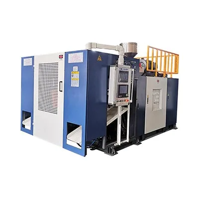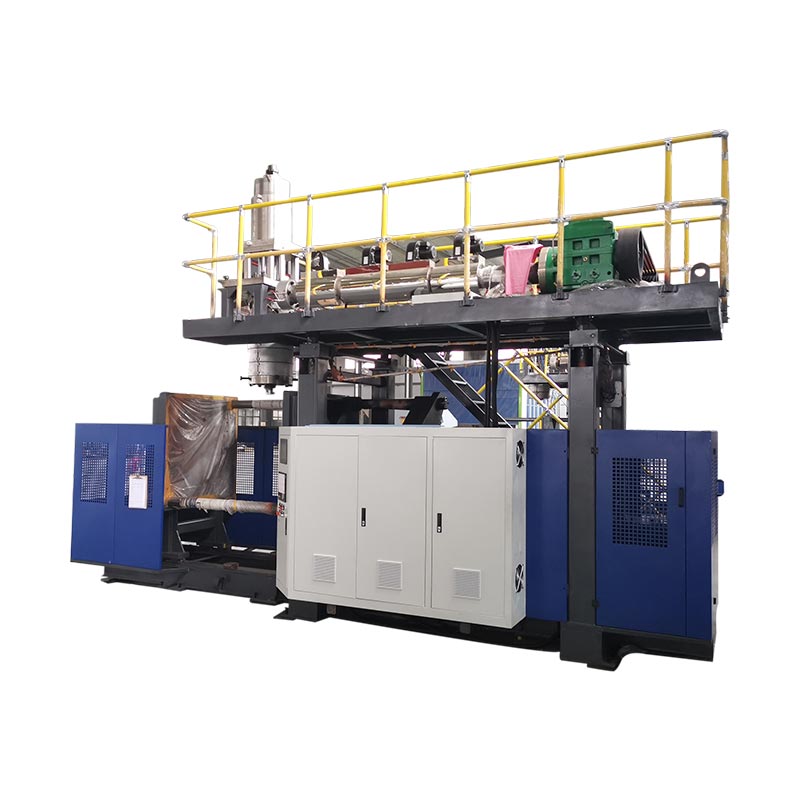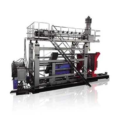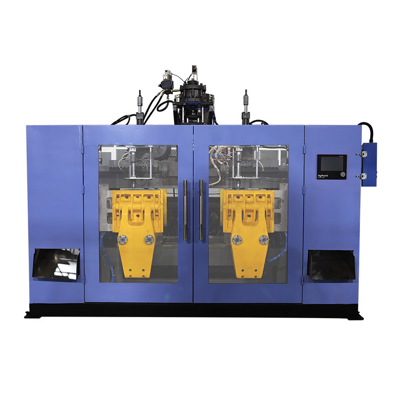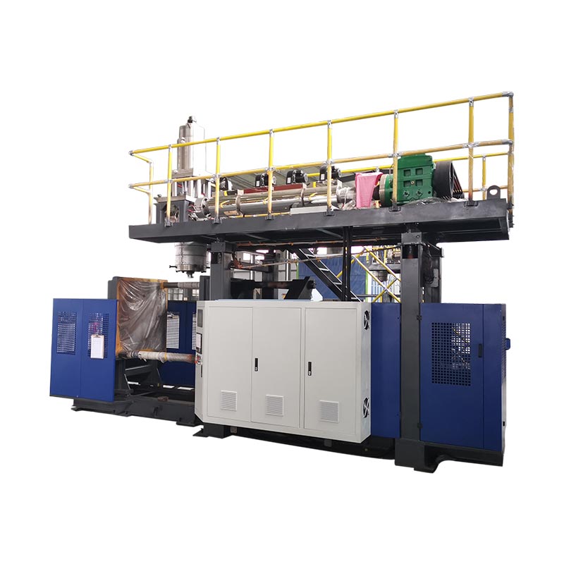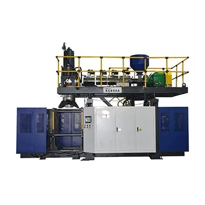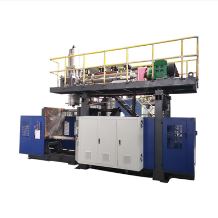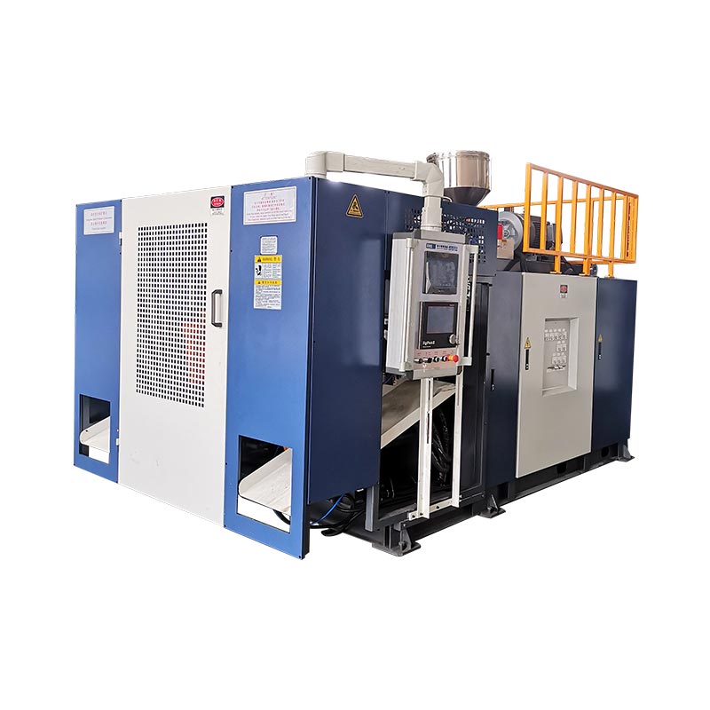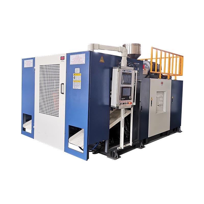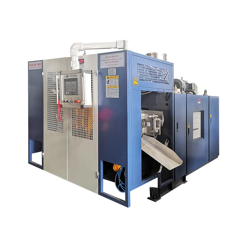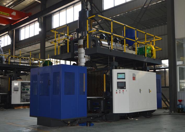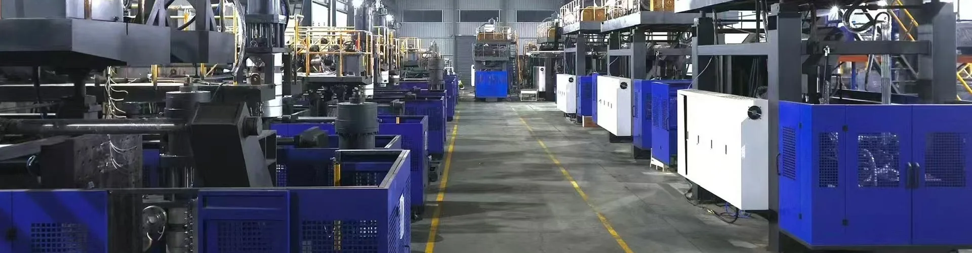
The main parts of a blow moulding machine are the feeding and extrusion system, die head, mold and clamp, blowing system, cooling circuits, drives and controls, and part-removal equipment. Their arrangement depends on the molding process and machine configuration. For extrusion blow molding, identify each component by its function and assembly before considering a replacement.
To identify a component, locate its assembly, confirm its function and collect the relevant technical information. A photograph or a familiar name rarely establishes whether two replacement parts will work on the same machine.
Four distinctions prevent expensive mix-ups
- The die head forms the plastic tube; the blow mold forms the container's exterior.
- A die pin or mandrel shapes the melt passage. A blow pin delivers air and may perform neck-related functions.
- A controller command, an actuator position and a measured bottle wall are different pieces of evidence.
- Matching a component name is only the beginning of replacement-part identification.
Identify the machine type before naming its parts
Confirm the process from the machine's identification and technical documents. Extrusion blow molding, injection blow molding and stretch blow molding make hollow products through different tooling arrangements. A component list that combines all three can send a buyer looking for hardware that the installed machine does not use.
In extrusion blow molding, or EBM, an extruder supplies molten polymer to a die head. The head forms a hollow tube called a parison, which the mold captures and inflates. Kinggle's blow molding machine guide explains the process categories and identifies extrusion blow molding as its equipment focus.
An injection blow molding machine instead forms a preform around a core rod before transferring it to the blowing stage. A PET stretch-blow system uses a preform and a stretching operation. Those distinctions matter when identifying tooling: an IBM core-rod assembly and a PET stretch rod should not appear on a generic EBM spare-parts list.
Keep assemblies, parts and process material separate
The term "blow molding parts" can mean machine components or the plastic products made by the process. State which meaning applies. A parison is plastic being processed, not a replaceable machine part. A cavity is a feature of the mold. A die head is an assembly that contains several components with their own identities.
Use the assembly hierarchy when requesting help: machine, system, assembly, then individual part. For example, "extrusion head, tooling assembly, mandrel" is more useful than "head pin." Add the drawing reference or original part number whenever it is available. This gives the supplier a starting point without relying on a local nickname.
| Component group | Function | Useful identification evidence |
|---|---|---|
| Feeding and extrusion | Supply, convey, melt and mix resin | Extruder drawing, screw/barrel specification, motor plate |
| Die head and parison tooling | Distribute melt and form the tube | Head model, tooling drawing, assembly revision |
| Parison control | Command changes to the tooling opening | Controller version, actuator and feedback identification |
| Mold and clamp | Capture the parison, hold the tool and define external shape | Mold ID, interface drawing, clamp assembly reference |
| Blowing and cooling | Inflate the parison and remove heat | Blow-tool drawing, air circuit and cooling-circuit map |
| Drive and control | Power, sequence and monitor functions | Schematics, device plates, software and parameter versions |
| Take-out and finishing | Remove and, where included, finish the product | Gripper/fixture drawing and approved line configuration |
Feed and melt the resin: hopper, screw, barrel and drive
The feed path starts before the screw
The hopper supplies material to the extruder feed section. A project may also include loaders, blenders, dosing equipment or a regrind return. Treat those as identifiable equipment with separate interfaces. The presence of a hopper does not prove that automatic conveying, drying or blending is included in the machine supply.
When output becomes irregular, record the resin grade, lot, blend and feeding behavior before blaming the screw. A restriction or an interruption in material delivery can affect what reaches the head. The maintenance team needs observations tied to the actual run, not simply a request for a larger extruder.
The screw, barrel and temperature system do different jobs
The rotating screw conveys and works the resin inside the barrel. Heating zones add heat under temperature control, while the process also develops heat through mechanical work. Temperature sensors provide feedback at their installed locations. A displayed barrel-zone temperature is therefore not a direct measurement of every part of the flowing melt.
Keep the heater and sensor identities separate. A low-temperature alarm can involve the power circuit, heater, feedback device, wiring or control setup. Replacing a heater without confirming the fault can leave the original problem unresolved. Use the actual wiring diagram and qualified electrical diagnosis rather than a universal resistance or temperature limit.
The drive must match more than a power rating
The motor, gearbox and coupling transmit motion to the screw. Their mechanical connections and operating requirements belong to the installed assembly. A motor with the same rated power is not automatically a suitable replacement, and a screw with the same nominal diameter may have different geometry or connection details.
For a screw or barrel inquiry, provide the original drawing, machine serial number and material application. For a drive inquiry, include the complete motor and gearbox plates plus the relevant assembly reference. Preserve the original orientation and connection information in photographs taken from a safe position. These records help distinguish the failed item from the larger assembly around it.
Form the parison: die head, die tooling and wall-thickness control
The die head receives melt from the extruder and distributes it toward the outlet tooling. The die and mandrel, sometimes described as die pin or core tooling, define the annular passage that forms the tube. Terminology varies by head design, so a named component should always connect back to a drawing.
The blow mold performs a different job. It closes around the hot parison and defines the container's exterior as air expands the plastic against the cavity. Ordering "a new mold head" without identifying whether the problem concerns the extrusion head, outlet tooling or blow mold creates avoidable ambiguity.
Continuous and accumulator heads have different material paths
A continuous-extrusion arrangement forms the parison from the continuing melt supply. An accumulator head stores a quantity of melt and discharges it during the cycle. The additional storage and discharge functions change the head assembly and its controls. A melt accumulator is also different from a hydraulic accumulator that stores energy in a fluid-power circuit.
Identify the head architecture before comparing seals, tooling, heaters or actuators. Matching the outlet diameter alone does not establish that the surrounding assembly, movement or control interface is compatible.
The controller is only one part of wall-thickness control
A parison-control system links a programmed profile to tooling movement through a controller, actuator and feedback arrangement. Moog's blow molding component overview describes controllers, actuators and servo components as separate elements of its solutions. These component families have different jobs within the control and motion system.
The practical implication is simple: a replacement screen or controller cannot be selected independently of the actuator, feedback and machine interface. Moog's overview describes component families; it does not identify which device is installed on a particular Kinggle machine.
Tooling position and final wall thickness must also remain separate. The bottle wall still depends on material behavior, part geometry and process conditions. Verify the molded part rather than treating a displayed profile as a wall-measurement report. The parison programming guide connects profile changes with measured product locations.
Shape and release the part: mold, clamp, blow system and take-out
The blow mold and the clamping unit should be identified separately. The mold is the product-specific tool. The clamping assembly supports and moves that tool and holds it closed during the required stages. Platens, guides, cylinders and any carriage mechanism belong to the machine configuration, not automatically to the mold purchase.
For replacement inquiries, a cavity photograph may identify the product but reveal little about the mounting interface. Include the tool ID and the relevant machine or mold drawing. The extrusion blow molding mold design guide explains why the cavity, pinch-off, cooling, blowing interface and removal method must work together.
A blow pin is not a die pin
The die pin or mandrel belongs to the melt-forming tooling. A blow pin belongs to the air-delivery and, in some configurations, neck-forming or calibration arrangement. Both may be called a "pin" on the shop floor, but they perform different jobs and have different interfaces.
Some products use a different blowing arrangement, including bottom blowing. Do not order a blow pin from the bottle volume alone. The product finish, tool geometry, mounting, movement and air connection must match the approved design. The exact functions of a pin or blowing assembly depend on that design.
Part removal extends beyond opening the mold
The removal system must take the formed product out without unacceptable damage or interference. Depending on the project, removal may involve a gripper, a robot, another handling mechanism or a defined manual operation. Flash removal, handle punching, leak testing and conveying may be separate equipment.
That boundary matters when a part reaches the next machine incorrectly. A marking or deformation can occur after the mold opens. Record where it first appears, which station or cavity produced it, and whether it was present before handling. Do not diagnose mold wear from a defect that has only been inspected after trimming and conveying.
Confirm the ordered take-out and finishing scope before requesting replacement fingers, fixtures or sensors. The automatic machine and complete-line guide separates machine functions from downstream supply. Automation should be identified by the actual configuration, not inferred from the word "automatic."
Support the cycle: hydraulics, cooling, sensors and controls
Power and fluid circuits
On a hydraulic machine, the motor and pump supply hydraulic power. Valves direct or regulate flow, and actuators produce movement. A servo-driven oil pump remains part of a hydraulic system. Calling it an electric motor does not make the whole machine all-electric.
The air system supports the specified pneumatic and blowing functions. Regulators, valves, filters, tubing and the blowing tool have different roles. A connection that looks correct still needs to match its circuit requirements. Identify hydraulic and pneumatic components from the schematic and complete device code, not just body size or port appearance.
Cooling has several separate loads
The mold needs heat removal, and the machine may have additional cooling loads such as hydraulic oil or other specified circuits. A chiller, tower or plant water system can sit outside the machine supply. Map the responsibility boundary before treating missing plant equipment as a missing machine component.
A normal reading at the main water supply does not prove that every mold branch has adequate circulation. Circuit identity and actual operating observations are more useful than a single line-wide assumption. The utility requirements guide explains how to keep machine, mold and auxiliary demands distinct.
The HMI, PLC and feedback devices are not interchangeable
The HMI is the operator interface. The PLC executes the machine's control logic, while field devices provide signals and carry out commands. A message on the HMI identifies a reported condition; it does not, by itself, establish that the screen is faulty or that a displayed device has failed.
Preserve the alarm, cycle step and relevant observations before clearing or changing anything. Use the HMI settings and alarms guide to organize that record. Controller, drive or feedback replacements may also require the correct program, parameters and calibration.
Safety-related devices require their specified replacement and validation process. In the United States, OSHA's hazardous-energy guidance addresses servicing risks from unexpected energization or stored energy. Follow the site's machine-specific procedure through authorized personnel. Neither an HMI stop nor a generic parts guide establishes safe access.
See how the parts differ on Kinggle continuous and accumulator machines
Real platform examples make the component map more useful. Kinggle's KGB5L product page describes a single-station continuous machine with a translational mold-shifting mechanism. Its table lists a 60 mm screw and Mitsubishi PLC is named in the feature description.
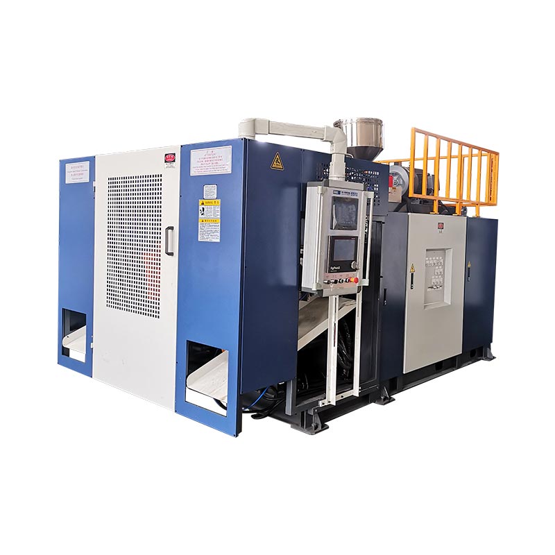
The KGB100B 120L page instead describes an accumulator-head platform. It lists a 100 mm screw and describes hydraulic servo operation, direct-pressure mold locking and wall-thickness control. Its storage and discharge arrangement gives the component discussion a different structure.

| Item | KGB5L | KGB100B | What the distinction changes |
|---|---|---|---|
| Published architecture | Single-station continuous extrusion | Accumulator-head extrusion | Head assembly and cycle relationships |
| Published screw diameter | 60 mm | 100 mm | Different extruder references; diameter is not a complete part specification |
| Published mold arrangement | Translational mold shifting | Fixed opening/closing arrangement described on the page | Identify the correct clamp and movement assembly |
| Replacement identity | Use this machine's as-built documentation | Use this machine's as-built documentation | No interchangeability follows from a shared component name |
Sources: the two linked Kinggle product pages. Configuration descriptions and screw diameters are catalogue information, not measurements from a customer's installed machine.
These examples show why "a Kinggle screw," "a hydraulic valve" or "a wall controller" is too broad an order description. Even within one machine family, the serial number, approved changes and current assembly revision matter. Product-page data can locate the platform, but it cannot replace the as-built bill of materials.
For purchasing, separate three records: what the catalogue describes, what the order included, and what is installed now. A later modification may have changed a drive, sensor or tool. Reconcile those records before selecting a replacement, especially when the old component no longer matches the original drawing.
During a service inquiry, mark the affected subsystem on an overview photograph and attach the readable component label separately. Link both images to the machine serial number. A close-up without installation context can hide whether the item belongs to the extrusion drive, hydraulic package or an auxiliary.
Identify the correct replacement before ordering
Begin with the observed problem and the part identity, not a conclusion that a component has failed. Uneven walls, slow movement or a temperature alarm can have several causes. Record the conditions and confirm the fault through the approved diagnostic process before purchasing a replacement.
The blow molding defects guide is useful for organizing product symptoms. For service intervals, use the preventive maintenance checklist alongside the installed machine's manual. A component overview should not prescribe one replacement age for every resin, duty cycle and operating environment.
| Record | Include | Why it matters |
|---|---|---|
| Machine identity | Model, serial number and identifying plate photo | Locates the build and its documentation |
| Assembly identity | System, assembly drawing, original part number and revision | Distinguishes one component from similar items |
| Device information | Complete manufacturer code and readable ratings | A partial code may omit a configuration difference |
| Connections | Relevant mounting, shaft, fluid, electrical or signal interfaces | Confirms more than visual resemblance |
| Change history | Approved replacements, modifications and software changes | Reconciles the original drawing with the current machine |
| Fault evidence | Alarm, cycle step, measurements, marked samples and safe photographs | Helps separate the reported symptom from the failed item |
Use a short, controlled identification sequence
- Locate the item in the machine's drawing or parts list and record its assembly reference.
- Capture the complete label and surrounding installation from a safe, permitted position.
- Match the relevant mechanical, electrical and fluid interfaces with the supplier's specification.
- Document substitutions or revisions and obtain the required technical approval before installation.
- After authorized replacement, verify the required setup, feedback, safety functions and product result before releasing production.
Different component classes need different evidence. A heater requires its specified electrical and installation details. A valve requires the correct circuit function and device configuration. A mechanical tool requires its drawing and interfaces. A control replacement requires version and parameter checks. A photograph can support these records but cannot establish every hidden requirement.
Request written confirmation of the exact supplied item and any approved substitute. Preserve the old and new identities in the service record. That record is more useful at the next failure than a purchase description that says only "one spare part for blow molding machinery."
An unreadable label needs more evidence, not a guessed part number. Use the drawing position, installation photographs and machine record to resolve the identity. Do not copy a code from a nearby machine simply because its component looks similar.
Frequently asked questions about blow molding machine parts
What are the main parts of a blow molding machine?
For an extrusion machine, the main groups are feeding and extrusion, the die head and tooling, parison control, mold and clamp, blowing, cooling, drives and controls, and product removal. The exact arrangement depends on the platform and project. Identify the process first, then use its assembly documents to distinguish standard equipment, selected options and separate auxiliaries.
What is the difference between a die head and a blow mold?
The die head handles molten polymer and forms the parison through its outlet tooling. The blow mold closes around that parison and defines the product's exterior during inflation. A mold cavity, die or complete head assembly is therefore a different order item. Give the assembly reference instead of relying on the word "mold" alone.
Is a blow pin the same as a die pin or mandrel?
No. A die pin or mandrel belongs to the melt-forming tooling and helps define the annular outlet. A blow pin introduces air and may have neck-forming or calibration duties in the specific design. The shared word "pin" does not make the components interchangeable. Use the actual tooling drawing to identify either item.
Are parts interchangeable between different blow molding machines?
Do not assume interchangeability from a common name, similar appearance or matching headline rating. The complete device code, assembly revision, mounting, connections and operating function must match. Controls can also depend on software, parameter and feedback compatibility. Any alternative should be approved for the installed configuration rather than inferred from a catalogue photograph.
What information is needed to identify a replacement part?
Send the machine model and serial number, original part number, assembly drawing reference, revision and clear label photographs. Include relevant interfaces, approved modifications and the observed fault. For control devices, preserve the version and configuration records too. This allows the inquiry to identify a particular item rather than a broad category of components.
Prepare a specific parts inquiry
For a Kinggle machine, start with the machine plate, assembly reference and readable component label. Add the problem record and relevant drawings, then send the package through the Kinggle contact page. Identifying the installed part is the first step toward confirming the correct replacement.