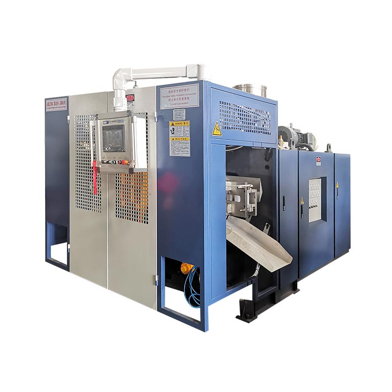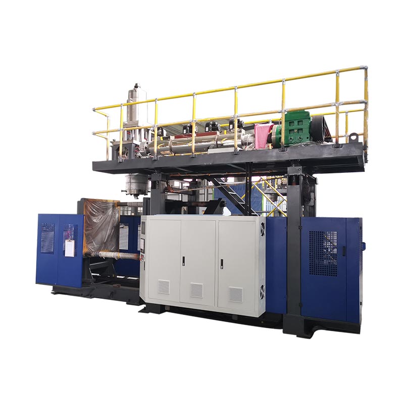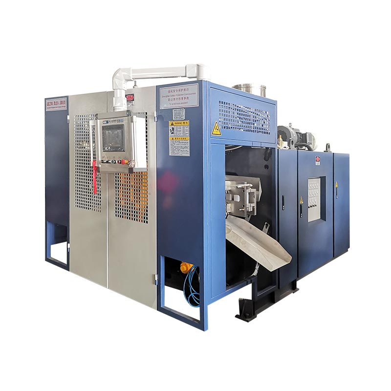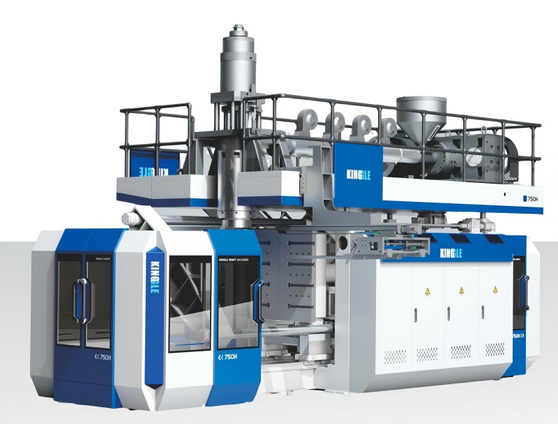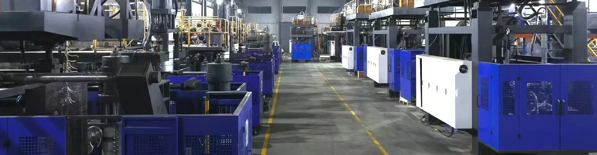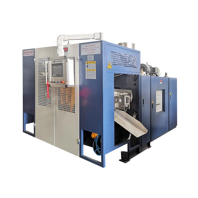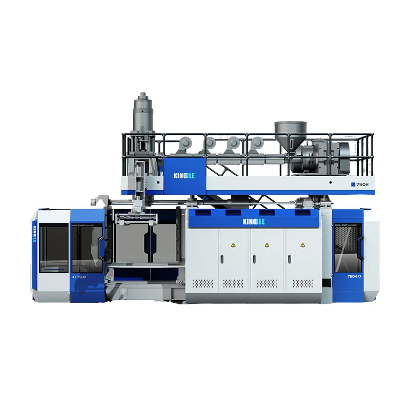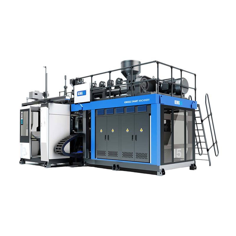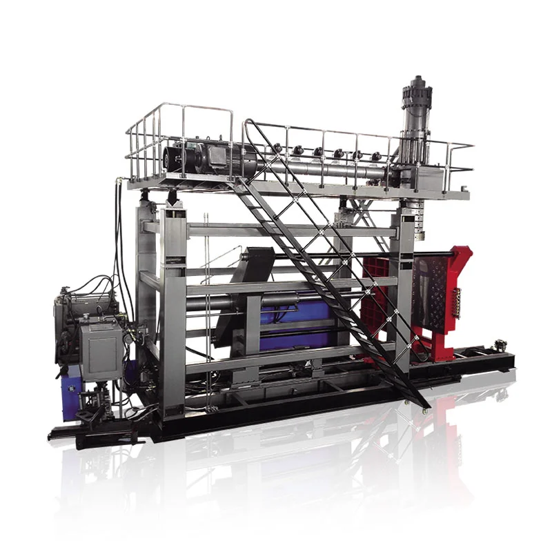
Automotive blow molding can produce hollow parts such as air ducts and fluid reservoirs. Selecting the equipment starts with the part drawing, specified resin and acceptance requirements. A machine's advertised container volume alone cannot establish whether it will form a particular duct, accommodate its mold or deliver the required finished output.
A useful purchase review follows the part through the complete process: forming, removal, trimming, assembly and inspection. Resolve mandatory product and tooling requirements before comparing nominal output or price. Otherwise, a fast molding cycle can conceal a production cell that still misses its delivery target.

Blow molding automotive parts: applications and process suitability
Group automotive parts by what they must do, rather than by the fact that they are hollow. A cabin air duct, an engine air-intake component and a liquid reservoir need different reviews. Their operating conditions and interfaces determine the questions that a machine proposal must answer.
| Part family | Inputs to establish | Equipment and tooling questions |
|---|---|---|
| Cabin HVAC ducts | Air path, connection geometry, installation space and specified functional checks | Can the proposed route form the body and leave accessible trimming and inspection locations? |
| Engine air-intake parts | Specified temperature, pressure or vacuum conditions, media exposure and connection requirements | Does the resin, forming route and complete cell suit those particular conditions? |
| Fluid reservoirs | Fluid, service conditions, ports, mounting features and acceptance criteria | How will the body, interfaces and any subsequent assembly be produced and verified? |
| Other hollow technical parts | Load cases, dimensions, assembly features and intended use | Is blow molding suitable, or should another forming or joining route be compared? |
Keep fuel-system projects on a separate approval path. For example, RISE describes plastic fuel-tank fire testing under UN Regulation 34, Annex 5, clause 5. That is a specific test scope, not a complete approval checklist. Establish the applicable market, requirements and approval responsibilities for the actual fuel-system project; a machine catalogue listing “car tanks” does not establish compliant fuel-tank production.
Blow-molded HVAC ducts: geometry, interfaces and machine requirements
For blow-molded HVAC ducts, review the air path and every connection together. A body that can be formed still needs openings that can be trimmed, located and checked. Custom plastic ductwork should therefore reach the quotation stage with both the molded geometry and the intended finished geometry defined.
Separate cabin ventilation from engine air-intake requirements
Do not transfer an engine air-intake material or test condition to a cabin duct simply because both carry air. Record the installation environment, approved material and required checks for the particular part. If pressure, vacuum, temperature cycling or fluid exposure matters, identify the relevant conditions in the project specification.
Review the finished connection, not just the molded opening
Mark connection ends, mounting datums, section changes and the proposed trimming locations on the drawing. Then check how the part will sit in a finishing or inspection fixture. A useful review question is whether the same datum system can locate the part consistently during trimming, measurement and assembly.
Specify any required flow, passage, fit or sealing check before defining the cell. These checks may need dedicated fixtures or separate stations. They should have an assigned supplier and acceptance method, rather than being assumed to come with the blow molding machine.
Choose the process route before choosing machine size
Discuss how the parison will reach the mold cavity before selecting a larger machine. A parison is the hot hollow tube that the process forms and inflates. Its handling and placement must suit the geometry.
Conventional extrusion versus 3D suction blow molding
Toray's technical explanation of 3D suction blow molding describes suction introducing the parison into a mold cavity for long, complex hollow shapes. This is a distinct process arrangement. A conventional extrusion blow molding machine with a part-removal robot should not be treated as equivalent evidence of that capability.
For an awkward path, request a forming-route review using the actual geometry and resin. Compare conventional extrusion blow molding, a specialized placement or suction route, and joined molded sections where appropriate. The comparison should address forming feasibility, interfaces and downstream work, rather than assuming that one route suits every automotive duct.
Keep melt delivery and drive configuration separate
Continuous extrusion and accumulator-head operation describe melt delivery. Parison placement describes a different part of the process. Hydraulic, servo-hydraulic and electric drives describe actuation. Comparing these on separate axes makes quotations easier to interpret and prevents an automation label from standing in for a forming capability.
Select blow molding resins for the actual automotive application
Specify the grade, not just the polymer family. “PA” or “PP” leaves open questions about reinforcement, modification, processing behavior and suitability for the intended part. Envalior's Durethan PA6 portfolio, for example, distinguishes blow molding grades and reinforced grades for tubes and air ducts. A family name does not identify an interchangeable recipe.
Match material preparation and plasticizing to the grade
Obtain the current grade-specific processing instructions. Check the proposed drying and feeding arrangement, moisture measurement where required, screw and head suitability, temperature control and any wear-resistant specification needed for the compound. These are items for technical confirmation, not reasons to publish one drying temperature for all engineering plastics.
Toray identifies melt viscosity and shape-retention stability as relevant to blow molding resin suitability. Record the material condition and process settings during a trial so a forming problem can be investigated against a known recipe. Do not accept a machine's published HDPE extrusion rate as proof of its delivery rate with a different resin.
Keep regrind within the approved recipe
Record the source, processing history and proposed proportion of regrind, together with customer permission and the checks needed to qualify the recipe. Test the intended production mix. A trial using only virgin resin does not establish performance with a later regrind addition.
Translate the part drawing into blow molding equipment requirements
Use a requirements-to-evidence table to review blow molding equipment. Each mandatory requirement needs a corresponding specification, drawing or trial record. Unresolved items should remain visible until the responsible party closes them.
| Requirement | Check in the proposal | Evidence and closure |
|---|---|---|
| Material and gross shot demand | Grade-specific plasticizing, usable shot and delivery; include process scrap rather than finished weight alone | Material record and representative forming trial |
| Mold installation | Envelope, mounting, mold thickness and mass, utilities and service access | Mold-machine interface drawing |
| Opening and removal | Opening space, required mold movements, gripper path and clearance for the hot part | Motion review and witnessed removal sequence |
| Critical wall regions | Head tooling, parison control and proposed inspection locations | Mapped measurements against drawing limits |
| Finished interfaces | Trimming, joining, assembly and positioning fixtures | Finished-part dimensional and functional checks |
| Accepted output | Complete cell, counting point, interruption rules and reject handling | Timed trial with accepted quantities and stop records |
How I would review an automotive blow molding project
For an automotive blow molding project, I would review the part drawing before discussing machine capacity. My starting questions would concern the material grade, operating environment, connection points and acceptance requirements. A machine's nominal container volume would remain a screening reference, not the basis for approving a duct or an irregular reservoir.
If a trial part met its weight target but failed a local wall-thickness check, I would investigate material distribution before increasing the overall part weight. I would compare the specified inspection locations with the parison profile, material preparation, tooling and recorded process settings. Adding material everywhere would remain a proposed change until the relevant part checks showed that it solved the problem.
The tooling review would cover more than whether the mold fits between the platens. I would check mounting, mold thickness, opening space, required movements and the complete part-removal path. Ports and mounting features would also need a clear plan for trimming, positioning and inspection after molding.
For a specified engineering-plastic grade, I would request its processing guidance and verify the proposed drying, feeding, screw and head arrangement. I would not use an HDPE throughput figure as proof of performance with another resin. Any proposed regrind recipe would remain subject to the applicable material and customer requirements.
Before approving the production cell, I would include downstream work in the trial plan. A molded duct still needs to pass the agreed trimming, assembly and inspection stages. I would record accepted output, interruptions and manual adjustments, then separate passed requirements from items needing correction or further evidence.
My recommendation would depend on those findings. A larger machine would not be my automatic response to a production shortfall; I would first establish whether the restriction came from molding, handling, finishing or inspection.
Blow mold design, wall distribution and critical interfaces
A finished part's weight is one measurement of the whole object. It cannot identify the thickness at a bend, connection or pinch-off. Establish inspection locations from the drawing and function, then compare measurements made in a defined part condition.
Separate longitudinal and circumferential control
Review longitudinal parison programming separately from wall distribution around the part's circumference. Toray describes radius wall-thickness control in its 3D suction process discussion. Confirm the proposed system's actual control functions; a large programming-point count alone does not demonstrate that every critical location will meet its limit.
For a local failure, map the measurement to its position on the part and investigate the relevant process and tooling variables. Keep changes traceable so their effects can be checked. The existing parison programming guide explains the control topic in more detail.
Carry the datums through finishing and assembly
Define how ports, trimmed edges and mounting features will be measured relative to the specified datums. Agree on the part's support and measurement condition. Review these interfaces with the mold and fixture suppliers using the mold design and machine-interface checks, rather than treating finishing as a separate issue after mold approval.
Define the complete automotive blow molding cell
Draw the route from resin preparation to the accepted-part counting point. Include removal, trimming, opening, joining, assembly and inspection only where the part needs them. For each operation, name the supplier, acceptance evidence and responsibility for integration.
Check station interfaces: how a part transfers, how it is located, what happens when a downstream station stops and how rejected parts are separated. A quotation should distinguish equipment supplied by the machine builder from equipment supplied by others. The automated-line configuration guide covers these supply boundaries.
Choose inspections from the part's function and specification. A leak test, where required, does not replace dimensional, passage, assembly or durability evidence. Avoid one generic test list for every automotive application.
Prove the part and the production process separately
Plan a representative trial around the drawing revision, approved material and intended recipe. Record the mold, setup, material lot and measurement plan. Keep accepted quantities, reject reasons, stoppages and manual interventions alongside the cycle record.
A supplier's machine test and a customer's production part approval serve different purposes. AIAG's public PPAP overview connects production part approval with consistently meeting design records and specifications during an actual production run at production rates. That scope is broader than demonstrating a machine motion or producing one acceptable sample.
| Activity | Question it addresses | Evidence to define | Does not by itself establish |
|---|---|---|---|
| Machine or cell FAT | Does the supplied equipment satisfy the agreed acceptance scope? | Contractual checks, configuration, trial conditions and open-item record | All finished-part functions or customer production approval |
| Part functional validation | Does the finished part meet the specified use requirements? | Applicable dimensional, assembly, functional and durability records | Sustained production performance outside the evaluated conditions |
| Customer production part approval | Does the intended production process meet the customer's applicable approval requirements? | Customer-defined submissions and production evidence, including PPAP where required | Approval for a changed material, drawing or process without the required review |
Set sample quantities, trial duration, measurement methods and any statistical criteria in the project acceptance plan. Do not borrow a universal Cpk target or run duration from a generic machine article. For the equipment portion, use the FAT planning guide to establish the agreed checks.
Close each requirement as passed, requiring corrective work and retest, or not yet verified. Assign an owner and closure evidence to the latter two categories. Keeping these statuses separate prevents an incomplete trial from becoming an apparent production release.
Compare output and cost at the accepted-part boundary
Count finished automotive parts that pass the agreed checks. State whether the target includes changeovers, interruptions and downstream operations, and use the same time basis for every station. See the production-rate calculation guide for the distinction between nominal cycles and accepted output.
Evaluating an HVAC duct cell beyond its molding cycle
For a hypothetical automotive HVAC duct project, I would start with a requirement of 95 accepted parts per scheduled hour. Assume a single-cavity mold, a 32-second molding cycle, 90% molding-stage run availability and a final accepted yield of 96% across the complete process.
The nominal molding rate would be 3,600 ÷ 32, or 112.5 parts per hour. Applying the assumed run availability would leave a molding-stage capacity of 101.25 parts per scheduled hour.
That figure would not establish the finished output. I would also compare the capacity of trimming, handling and inspection. The table below shows two planning scenarios, assuming no additional transfer losses or interactions between station stoppages. Both downstream capacity figures use scheduled hours and already allow for the assumed station interruptions; the 96% yield is applied once at the end.
| Planning measure | Initial downstream scenario | Revised downstream scenario |
|---|---|---|
| Molding-stage capacity | 101.25 parts/hour | 101.25 parts/hour |
| Downstream processing capacity | 90 parts/hour | 105 parts/hour |
| Assumed final accepted yield | 96% | 96% |
| Projected accepted output | 86.4 parts/hour | 97.2 parts/hour |
| Required accepted output | 95 parts/hour | 95 parts/hour |
In the initial scenario, downstream capacity would limit the cell to 90 parts per hour before the final yield allowance. Projected accepted output would therefore be 90 × 0.96 = 86.4 parts per hour, below the requirement.
I would next evaluate a downstream arrangement capable of processing 105 parts per hour. With the molding stage then limiting supply, projected accepted output would become 101.25 × 0.96 = 97.2 parts per hour.
The revised calculation would exceed the target by only 2.2 parts per hour. I would treat that as limited planning headroom, not proof of an approved production rate. A representative cell trial would still need to establish the actual cycle, interruptions, downstream performance and accepted yield.
This comparison would direct the engineering review toward the finishing and inspection arrangement before requesting a larger blow molding machine.
Compare the same production scope
Separate the machine, mold, material preparation, finishing fixtures, inspection, integration and trial costs in each proposal. A machine-only price cannot be compared directly with a complete-cell price. Evaluate additional capacity against accepted output and project demand; do not assume that a larger machine will remove a downstream bottleneck.
Prepare an automotive-part RFQ for Kinggle
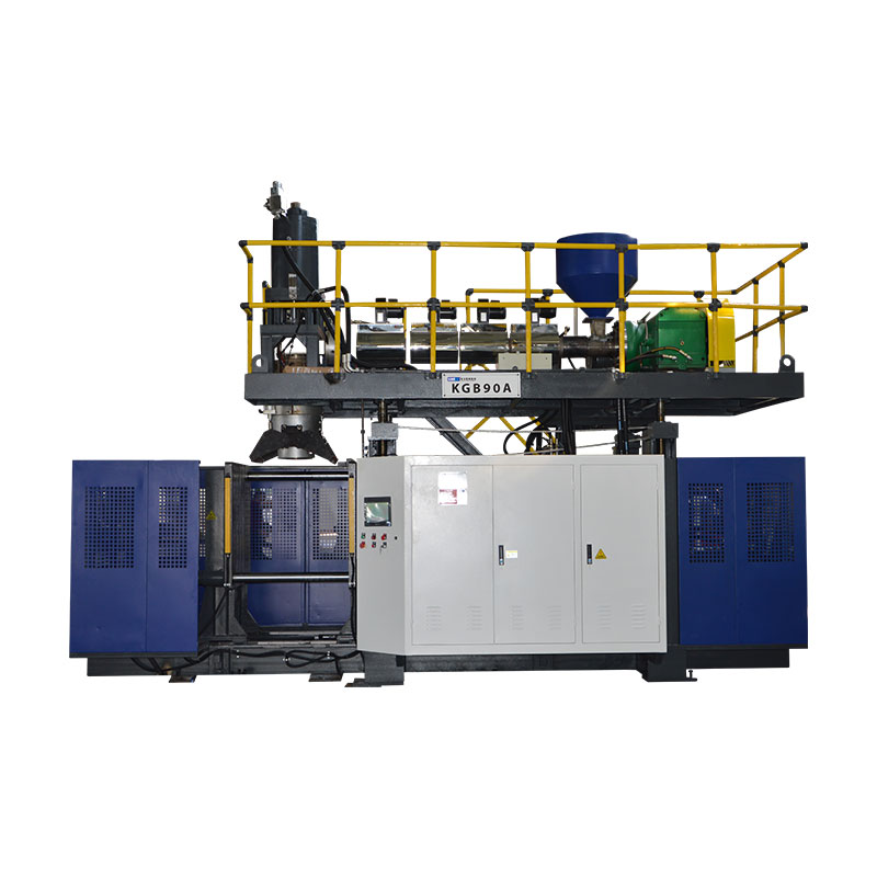
Kinggle's published accumulator platforms provide specification references for an initial discussion. They are not automatic selections for the hypothetical duct example or for every automotive part. The proposed material, mold and complete production scope still need a technical review.
| Reference field | KGB80A | KGB100B |
|---|---|---|
| Advertised maximum container capacity | 30 L | 120 L |
| Clamping force | 215 kN | 440 kN |
| Mold platen size, W × H | 750 × 860 mm | 1,200 × 1,200 mm |
| Maximum mold size, W × H | 520 × 860 mm | 920 × 1,200 mm |
| Mold thickness | 360 to 420 mm | 510 to 600 mm |
| Listed application connection | Auto parts pipelines | Auto parts and car tanks |
The table reproduces selected fields from the linked Kinggle product pages. Platen size and maximum mold size are different fields. Neither confirms a complete motion envelope, grade-specific output, specialized suction process or fuel-system approval. Request the interface drawing and configuration for the proposed build.

Send a review package, not just a requested machine volume
- 3D and 2D part drawings with revisions, finished geometry, datums and critical wall or interface requirements.
- The specified resin grade, approved production recipe and relevant processing instructions.
- Part weight, planned mold arrangement, existing tooling information and the proposed finishing sequence.
- Required accepted output with its time basis, annual demand, product mix and inspection requirements.
- Site conditions and a clear list of who supplies the mold, auxiliaries, finishing, inspection and integration.
These inputs let the technical review address fit, unresolved requirements and trial conditions before a machine configuration is finalized.
Frequently asked questions
Can every automotive air duct be made on a conventional blow molding machine?
No. Review the geometry, specified resin, interfaces and tooling access. Some shapes warrant evaluation of specialized parison placement, suction blow molding or joined sections. A conventional machine with a take-out robot does not by itself establish those forming capabilities.
Is accumulator volume enough to select a machine for an automotive part?
No. Usable shot demand, material-specific delivery, mold installation, opening space, required movements, part removal and downstream work also need review. An advertised container volume is a screening reference, not a complete selection method for an irregular technical part.
Can an HDPE machine process a specified engineering-plastic grade?
That requires a grade-specific review of material preparation, plasticizing, head tooling, controls and the proposed process. A published HDPE extrusion rate does not prove output with another resin. Confirm the configuration and run a representative trial with the intended material.
Why can a part meet its weight target but fail a wall-thickness check?
Weight describes the whole part, while a thickness check measures a location. Material can be distributed differently between regions without a corresponding change in total weight. Map the failed location and investigate the relevant material, tooling and process conditions before deciding how to correct it.
Does passing a machine FAT complete customer production part approval?
No. FAT covers the agreed equipment acceptance scope. Finished-part validation and customer production approval require their own applicable evidence. Where PPAP is required, confirm the customer's submission and production-run requirements rather than treating equipment delivery as approval.
Is buying an automotive blow molding machine the same as sourcing custom blow-molded parts?
No. Equipment procurement concerns the machinery, tooling interfaces, integration and acceptance scope for a production process. Sourcing finished parts concerns a manufacturer's responsibility for producing and supplying those parts. Clarify which scope is being requested before comparing suppliers.
For an automotive-part equipment review, send the drawing and material requirements through Kinggle's contact page or email sales@kinggle.com. Telephone: +86-574-87103665. Company information is available on the Kinggle About page.
Approve the production route before committing to the machine
Start with the part and material, settle the forming route, and turn the drawing into explicit equipment and validation requirements. Then compare complete proposals at the accepted-part boundary. A mandatory fit problem needs resolution; a faster cycle or lower purchase price cannot close it.