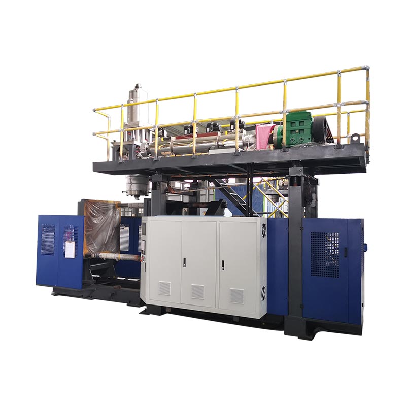
Calculate blow molding machine production rate by dividing 3,600 by the interval between output events in seconds, then multiplying by the parts produced at each event. To estimate good parts per shift, apply the measured quality yield and actual running hours, and check that extrusion and downstream equipment can support the result. A dry-cycle specification alone does not establish finished-bottle output.
Base a capacity decision on accepted parts across the planned production period, not the fastest cycle on a specification sheet. For extrusion blow molding, the output calculation must account for the bottle, tooling and material demand. PET stretch-blow ratings are not a substitute for those checks.
How do you calculate blow molding output per hour?
Start with a counting event that an observer can identify. For this guide, an output event is a release of molded parts from one operating mold. Record the average interval between those events across the complete machine, together with the number of parts released each time.
If two parts leave the machine every 16 seconds, the calculation is 3,600 ÷ 16 × 2 = 450 parts per running hour. This is an illustrative calculation, not a Kinggle machine rating. It counts molded parts before subtracting rejects and assumes the stated interval can be sustained.
Use the right cycle time formula
The manufacturing cycle time of one station is not always the interval between outputs from the complete machine. Similarly, seconds per part is not the same quantity as seconds per two-part molding event. Write the unit beside every input before entering it into a spreadsheet.
For a measured period, the equivalent cycle time equation is elapsed running seconds divided by the number of output events. If the events produce different quantities, use the direct count method instead: total molded parts divided by running hours. Vorne's OEE glossary likewise defines actual run rate using total count and run time.
To calculate cycle time from a recording, measure between matching points. Ten consecutive timestamps contain nine intervals, not ten. For uneven cycles, divide the total elapsed time by the actual interval count rather than averaging a selection of fast cycles.
A basic Excel entry is =3600/A2*B2, where A2 contains seconds per event and B2 contains parts per event. If your cycle time calculation formula already returns seconds per individual part, use =3600/A2. Multiplying that result by the cavity count would count those cavities twice.
Name the result according to its inputs. An ideal interval gives an ideal rate. A representative measured interval gives an observed running rate. Neither automatically includes changeovers or a complete shift's stops. Keep the distinction visible when transferring the result into a quotation or production schedule.
Count stations, heads and cavities without double-counting
A station, a die outlet and a mold cavity describe different parts of the production arrangement. Kinggle's multi-head versus multi-cavity guide separates them: outlets form parisons, cavities form parts, and stations are the mold-and-clamp positions. Their numbers are not interchangeable multipliers.
Imagine two stations, each producing two parts per release. Station A releases at 0 and 32 seconds; station B releases at 16 and 48 seconds. Each station repeats every 32 seconds, but the complete machine releases a pair every 16 seconds. The following timing is invented solely to explain the calculation.
| Counting basis | Calculation | Gross output |
|---|---|---|
| Complete machine | 3,600 ÷ 16 seconds × 2 parts | 450 parts/h |
| Separate station totals | 3,600 ÷ 32 seconds × 2 parts × 2 stations | 450 parts/h |
| Incorrect double count | 3,600 ÷ 16 seconds × 2 parts × 2 stations | 900 parts/h, incorrectly |
The last calculation counts the second station twice. Its contribution is already included in the 16-second whole-machine interval. In a real timing record, label every event with its station so another person can reconstruct the calculation.
Do not assume that adding a second station preserves the same timing under load. The proposed arrangement still needs enough material delivery, cooling and handling capacity. Compare the actual operating schedule, not just the station count. Kinggle's single- and double-station comparison provides related configuration context.
Count active positions as well. If one cavity is intentionally out of service, its nominal presence in the mold does not create output. If it produces a defective bottle, that bottle belongs in the gross count and the reject count. Reducing the cavity input and subtracting the same rejected bottle again would understate output.
For a mixed arrangement, calculate each stream separately and add the results. A shared average is useful only when its event count and parts count represent the same observation period. This matters when one station stops while the other continues, or when the two molds produce different parts.
Turn running-hour output into good parts per shift
A buyer scheduling deliveries needs a different number from an operator checking machine speed. Start with the whole shift, identify time when production is not scheduled, and then record stops during the remaining planned production period. State that time boundary before quoting a shift total.
The public scope of ISO 22400-2:2014 describes manufacturing KPIs through their formulas, constituent elements, time behavior and units. It is a useful reference for disciplined measurement. This article uses the practical definitions below; it does not claim that a machine or trial is certified to that standard.
Under the Vorne OEE framework, changeovers inside scheduled production are availability losses. They do not disappear simply because they were planned. Time with no intention to produce, such as an excluded meal break, has a different role. Define the treatment before the trial rather than changing it to improve the final percentage.
Quality yield here means accepted parts divided by total molded parts, with both counts taken over the same period and process boundary. If acceptance occurs after leak testing, unfinished work waiting for that test is not yet confirmed good output. Document any starting or ending work in progress.
When to use an OEE calculation
When starting from an ideal rate, account for availability, speed loss and quality. Vorne's calculation guide gives the following relationships. The ideal rate must describe the same product and active configuration as the counted output.
| Factor | Calculation |
|---|---|
| Availability | Running time ÷ planned production time |
| Performance | Observed gross running rate ÷ ideal gross running rate |
| Quality | First-pass good count ÷ total count |
| OEE | Availability × performance × quality |
Good output can therefore be calculated as ideal rate × planned production hours × OEE. Use fractions, not whole percentages, in that multiplication. An OEE of 78.4% enters the formula as 0.784.
Choose either the ideal-rate route or the observed-rate route. An observed running rate already reflects the speed achieved during that running period. Multiplying it by another performance factor for the same speed loss would subtract the loss twice. Likewise, a measured good-parts-per-shift figure already includes the stops and rejects within that shift; do not apply a second blanket efficiency discount to describe the same shift.
Check whether the extruder can support the target output
An output estimate also creates a material requirement. Use the gross mass processed for each molded part, not only the weight of the finished container. For this calculation, gross mass includes the material that becomes the container and its associated trim, allocated consistently across the parts produced.
Suppose the hypothetical 450-part/h arrangement processes 90 g per molded part. Its running demand is 450 × 90 ÷ 1,000 = 40.5 kg/h. If the finished bottle weighs 70 g, using only its net weight would produce a lower figure of 31.5 kg/h. Both numbers are derived from illustrative assumptions, not a measured bottle project.
The 9 kg/h difference is the assumed material associated with trimming. Its eventual recovery does not remove the original processing requirement. Keep a separate calculation for purchased resin, recovered material and disposal; the extruder load calculation concerns the material passing through the process.
Kinggle's head-layout guide also connects event mass with available extrusion capacity. Adding cavities may increase parts per event, but it also increases the mass required for that event. A larger nominal cavity count cannot by itself resolve a material-supply limit.
Compare running demand with a throughput reference applicable to the material and proposed setup. Do not dilute the demand by averaging it across a lunch break or shutdown. The machine must support the material rate while it is producing, even if the shift-average rate is lower.
A preliminary material ceiling is available kg/h divided by gross kg per part. It is only a screening calculation. It does not establish cooling time, acceptable wall distribution, dimensional stability or the output of the trimming and inspection equipment. Those require their own checks.
For the initial review, put molding, extrusion and downstream capacities into compatible units and compare them. The smallest supported rate identifies a candidate constraint, not an automatic production guarantee. Include intermediate buffers and interruptions when planning a complete line, then verify the proposed arrangement with the intended product.
Worked example: from cycle time to a shift production plan
The following worked example uses hypothetical inputs for an extrusion blow molding arrangement. It is not a KGB2L performance rating. Keep the same timing, part-count and quality assumptions throughout the calculation so the running rate, shift total and material demand can be checked against one another.
Assume an eight-hour shift contains a 30-minute break when production is not scheduled. Another 30 minutes of stops occur during scheduled production. The remaining running time is seven hours. During that running time, two parts leave the machine every 16 seconds on average, and 96% pass inspection without rework.
| Step | Calculation | Result |
|---|---|---|
| Planned production | 8 h minus 0.5 h excluded break | 7.5 h |
| Running time | 7.5 h minus 0.5 h recorded stops | 7 h |
| Gross running rate | 3,600 ÷ 16 × 2 | 450 parts/h |
| Total molded parts | 450 × 7 | 3,150 parts |
| First-pass good parts | 3,150 × 0.96 | 3,024 parts/shift |
| Good output per planned hour | 3,024 ÷ 7.5 | 403.2 parts/h |
| Good output per clock hour | 3,024 ÷ 8 | 378 parts/h |
| Running material demand | 450 × 90 g ÷ 1,000 | 40.5 kg/h |
Notice that 450, 403.2 and 378 can all describe the same scenario. They answer different questions. The first concerns gross output while running. The second spreads accepted output over planned production time. The third spreads it over the whole shift. A report that omits the denominator leaves room for a misleading comparison.
Cross-check the result with OEE
For this example only, assume an ideal event interval of 14 seconds with two parts per event. That is an ideal rate of about 514.286 parts/h. Availability is 7 ÷ 7.5; performance is 450 ÷ 514.286; quality is 0.96. Their product is 0.784, or 78.4% OEE.
Applying the Vorne OEE calculation method, 514.286 × 7.5 × 0.784 returns approximately 3,024 good parts. The small displayed rounding does not change the underlying result. The 14-second ideal interval is an example assumption, not a catalogue dry-cycle value.
For an illustrative order of 12,000 accepted parts, 12,000 ÷ 3,024 gives about 3.97 such shifts. Four shifts provide a calculated 12,096 parts under these assumptions, before additional order-specific losses. This is a planning scenario, not a delivery commitment or a reason to omit startup validation.
If recorded stops increase from 30 to 60 minutes, running time falls to 6.5 hours. With other assumptions unchanged, output becomes 450 × 6.5 × 0.96 = 2,808 good parts. The order then exceeds four shifts. This comparison shows why a small change in available running time can affect scheduling without any change to the molding cycle.
Try your own production rate calculation
Defaults reproduce the hypothetical example. Enter an observed average interval during running time, not a dry-cycle rating. Do not multiply by stations again if the interval already covers the complete machine. Data stays in this page.
- Gross parts per running hour
- 450
- Estimated good parts per shift
- 3,024
- Good parts per planned hour
- 403.2
- Material demand while running
- 40.5 kg/h
Results are estimates, not guaranteed output. Decimal part counts express an expected average. This calculator does not model buffer storage, order startup, variable cavity counts or a separate ideal-rate OEE mode. If scripts are disabled, the displayed results remain the default example.
What Kinggle's KGB2L specifications tell you about capacity
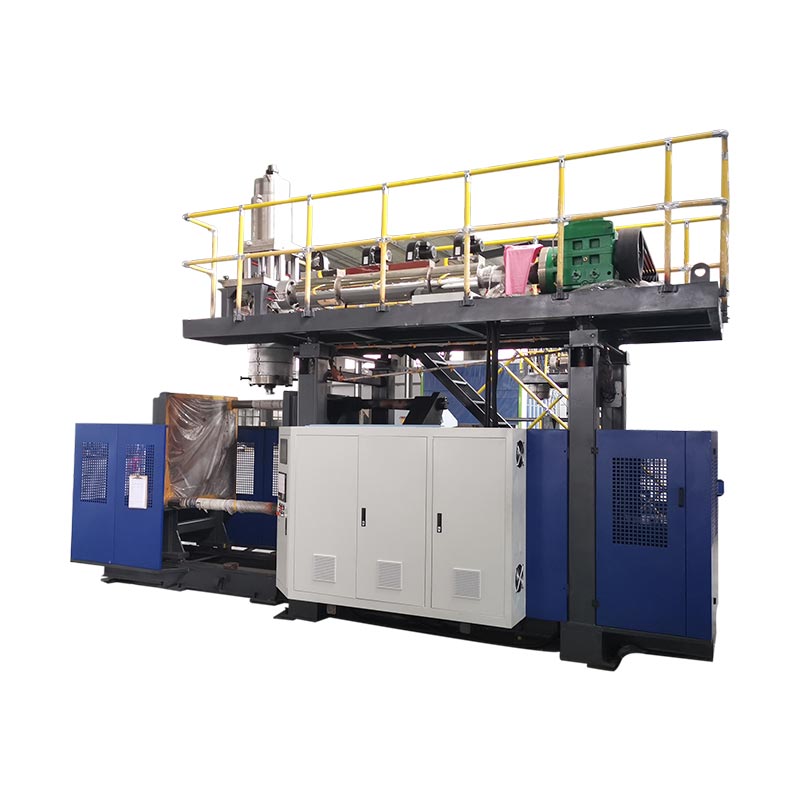
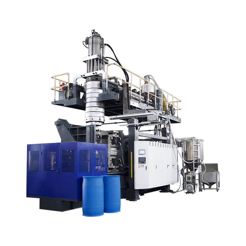
The KGB2L 2L single-station blow molding machine provides a concrete example of how to read a specification sheet. Its published values describe several different limits. Container volume, dry-cycle output, material throughput and mold dimensions each answer a different selection question.
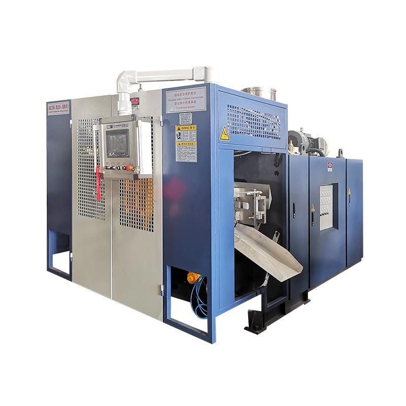
| Published parameter | Value | Question it helps answer |
|---|---|---|
| Maximum container capacity | 2 L | Is the proposed product within the stated volume category? |
| Output (dry Cycle) | 600 PC/HR | What dry-cycle reference does the catalogue state? |
| HDPE melting capacity | 30 kg/h | What material-rate reference is available for preliminary screening? |
| Screw diameter | 50 mm | Which extrusion platform is being discussed? |
| Maximum mold size, W × H | 360 × 380 mm | What published mold envelope must the tooling review consider? |
| Double-head center distance | 130 mm | What spacing reference needs comparison with the proposed layout? |
The dry-cycle field is not a trial report for a specific 2 L bottle. Do not relabel 600 PC/HR as 600 accepted containers per hour. The product's resin, weight, cavity arrangement, cooling requirements and acceptance criteria still need to be established.
Use the 30 kg/h HDPE reference for a separate mass check. At the worked example's assumed 90 g gross mass per part, dividing 30 by 0.09 gives about 333.3 molded parts/h as a material-only screening ceiling. The example's 450 parts/h would require 40.5 kg/h, above that published reference.
This calculation does not promise 333.3 parts/h from the KGB2L. It flags that the example's mass and target rate cannot be justified using the listed 30 kg/h reference. A project review would need a different supported configuration, revised product assumptions or a different output target.
Nor does the double-head spacing prove that any two bottles will fit. Check the actual mold drawing against the published envelope and the complete tooling arrangement. For larger or wider products, the number of usable cavities must follow the drawing rather than a preferred output multiplier.
When requesting a recommendation, send the drawing, material grade, net and gross weight estimates, required accepted output and intended shift pattern together. This allows the supplier to check capacity assumptions against the proposed hardware instead of answering an isolated question about bottles per hour.
Verify the output before you commit to a machine
Make accepted output the basis of the capacity agreement. Bottles leaving the mold and bottles cleared for packaging are different counts. Before testing, specify the inspection point and the requirements a bottle must meet to enter the accepted total. Otherwise, the trial can meet its molding target while leaving the delivery requirement unresolved.
For the KGB2L, keep the published 600 PC/HR dry-cycle figure separate from the bottle-output commitment. Confirm the material, bottle weight, active cavities and acceptance requirements before agreeing on production capacity. A dry-cycle figure alone is insufficient for a bottle-delivery schedule.
When a trial misses its target, diagnose the shortfall before increasing speed. Record output intervals, stops and rejected parts separately. Check for waiting time at parison delivery, cooling time inside the mold, and queues before trimming or leak testing. These observations distinguish a molding constraint from a downstream constraint.
Evaluate one adjustment at a time and retain the before-and-after records. Judge the change by accepted output over comparable observation periods, not by a shorter displayed cycle alone. Record material and tooling conditions beside the result. If the count rises but more bottles fail inspection, the adjustment has not necessarily improved usable capacity.
Keep a record another person can check
- Identify the drawing revision, resin grade, material mix, target weight and cavity arrangement.
- Agree on the acceptance checks and the position where good parts will be counted.
- Record start and finish times, scheduled exclusions, production stops and their reasons.
- Record total molded parts, first-pass accepted parts and rejects without counting reworked parts twice.
- Compare the observed rate, gross mass demand and downstream output over matching periods.
- Keep the agreed settings, observations and unresolved limitations with the trial report.
Define what happens at the start and end of the measurement window. A short observation taken after warmup answers a different question from an entire order that includes startup and a mold change. Both can be useful, but only when the report identifies what was excluded.
Use the blow molding machine factory acceptance test guide to develop the wider inspection record. An output calculation supports acceptance; it does not replace product inspection, equipment checks or the purchase agreement.
| Record field | What to enter |
|---|---|
| Product and configuration | Drawing revision, material, weight, active cavities and stations |
| Measurement boundary | Clock start/end, planned time, running time and count location |
| Counts | Total molded, first-pass good, rejected and unfinished parts |
| Conditions | Recorded settings, cooling and air conditions, staffing and auxiliaries |
| Outcome | Good parts per stated hour or shift, limitations and agreed follow-up |
Discuss a product-specific capacity estimate with Kinggle
Require an output estimate tied to the product drawing and proposed machine configuration. The written proposal should state where accepted parts are counted, how long the measurement runs and which production conditions apply. Without those details, a bottles-per-hour figure is not a sound basis for comparing equipment offers.
Send your bottle drawing or sample details, material grade, required good output and shift schedule through Kinggle's official contact page. Where a value is still an estimate, label it so the next review can resolve it.
Ningbo Kinggle Machinery Co., Ltd.
Email: sales@kinggle.com
Telephone: +86-574-87103665
Yuyao City, Ningbo, Zhejiang, China. Contact details checked against the official contact page.
Frequently asked questions
How many bottles can a blow molding machine produce per hour?
There is no single output figure for every machine and bottle. Divide 3,600 by the whole-machine output interval in seconds, then multiply by the molded parts per event. Apply the first-pass quality yield for good output during running time. For shift planning, also include recorded stops and confirm the material and downstream capacity.
Does a double-station machine always double production?
No. Two stations do not establish the production rate without their actual timing and configuration. If the measured whole-machine interval already includes alternating releases from both stations, do not multiply by two again. Compare each station's timing, active cavities and material demand before estimating the combined output.
Is dry-cycle output the same as finished-product output?
No. A catalogue field labeled dry-cycle output does not establish the accepted output of a specified container. Kinggle's KGB2L page lists 600 PC/HR under that label. A bottle-specific output claim needs the material, tooling, weight, operating conditions and inspection criteria, together with a defined measurement period.
How does container weight affect production capacity?
Weight affects the material needed at a given production rate. For extrusion screening, use gross processed mass per molded part, including its allocated trim, rather than only finished-bottle weight. Divide available material throughput by that gross mass for a preliminary ceiling. This calculation alone does not establish an achievable molding cycle or accepted output.
What information is needed for an accurate output estimate?
Provide the product drawing, material grade, net and gross weights, cavity and station arrangement, target accepted output and shift schedule. Include the acceptance checks and downstream equipment. If trial records exist, supply total counts, good counts, timing and stop reasons. Keep assumed values separate from measured results so the supplier can identify the remaining evidence gaps.
Before placing an order, agree on accepted output, trial conditions and the counting method in writing. Use the resulting production record as the basis for the delivery schedule.