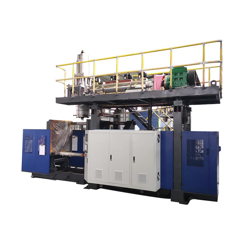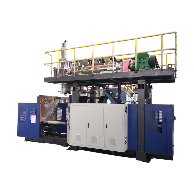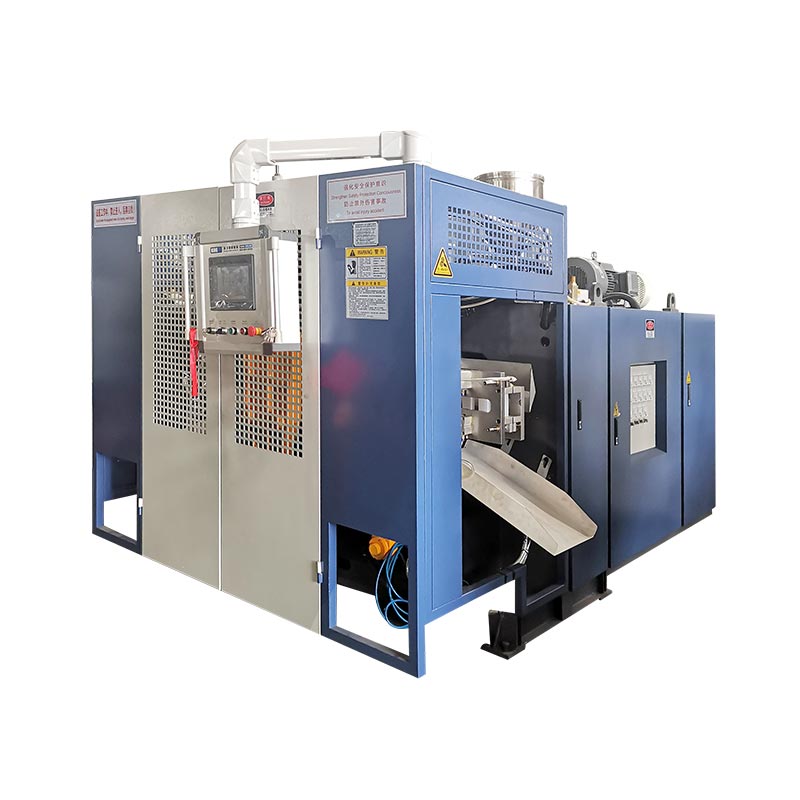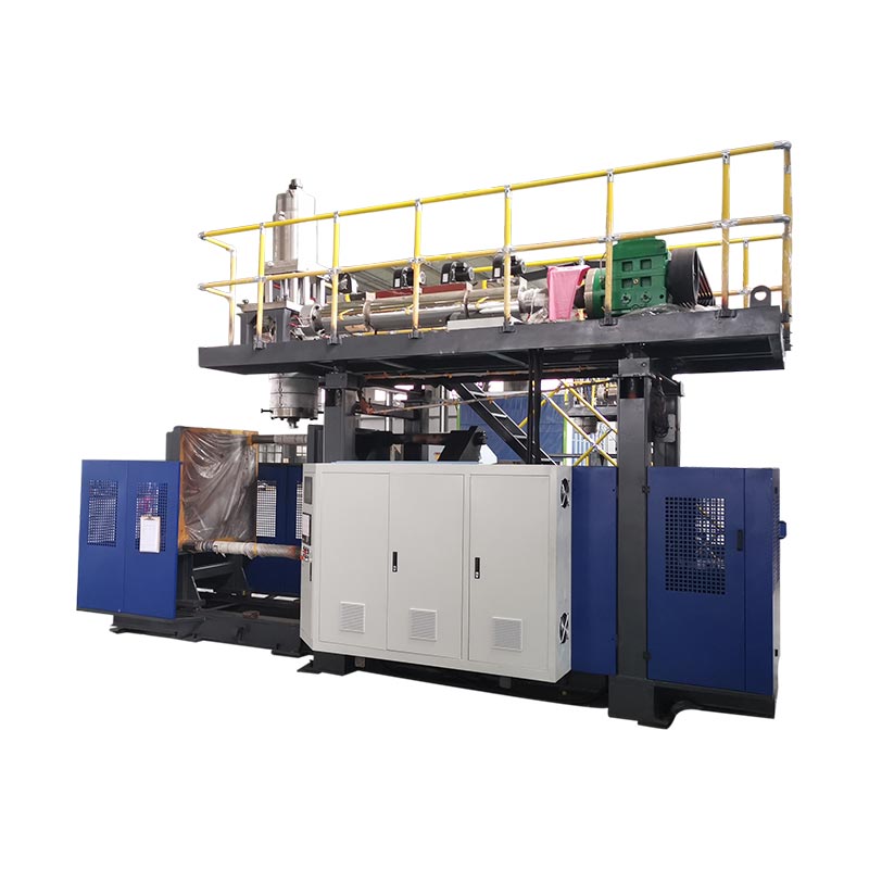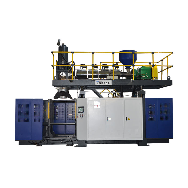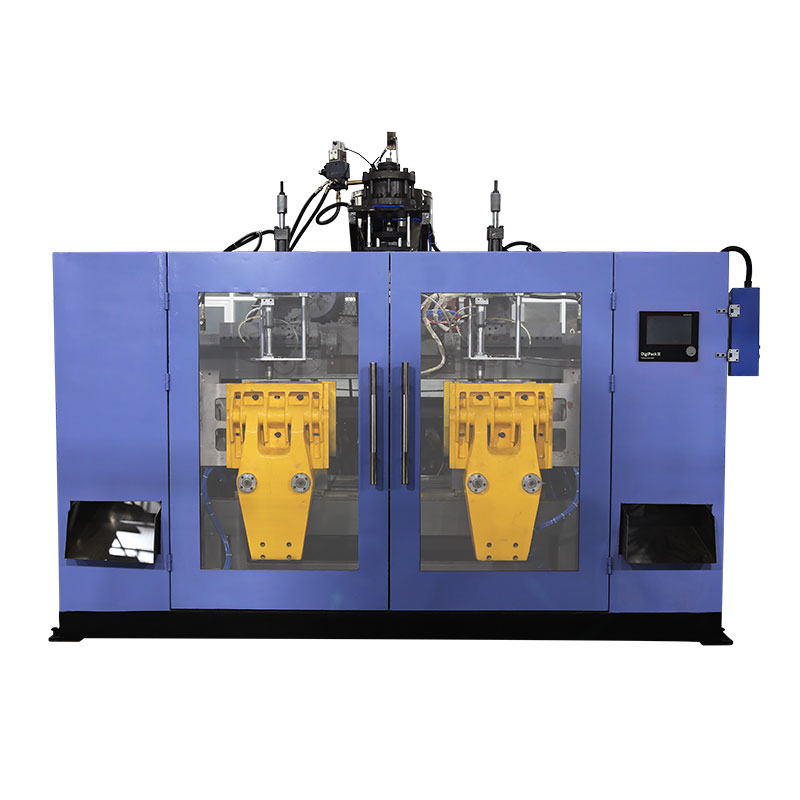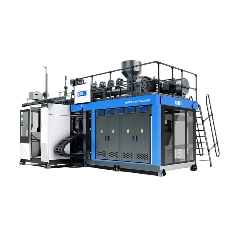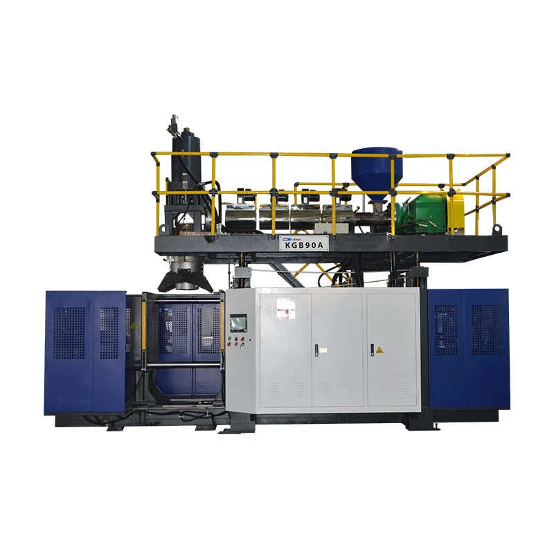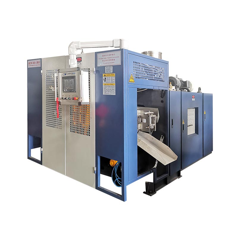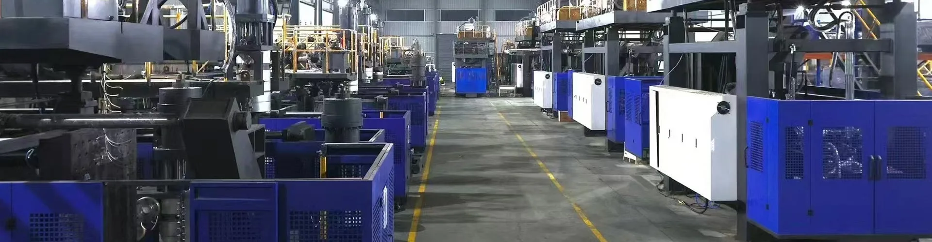
A 1000L IBC blow molding machine forms the plastic inner receptacle. It does not prove the complete IBC by itself. Select and accept the machine against the approved inner bottle, cage, pallet, closures, material system, mold, downstream assembly and required package tests.
Large capacity makes an IBC project look like a machine-sizing exercise. The difficult work sits at the interfaces. The top opening must meet the closure. The bottom outlet must meet the valve and cage access. The molded body must sit correctly on the pallet. The cage must protect the inner receptacle without creating damaging contact.
This guide turns those interfaces into machine inputs and factory test evidence. It uses Kinggle's current 1000L IBC platform as the published equipment reference.
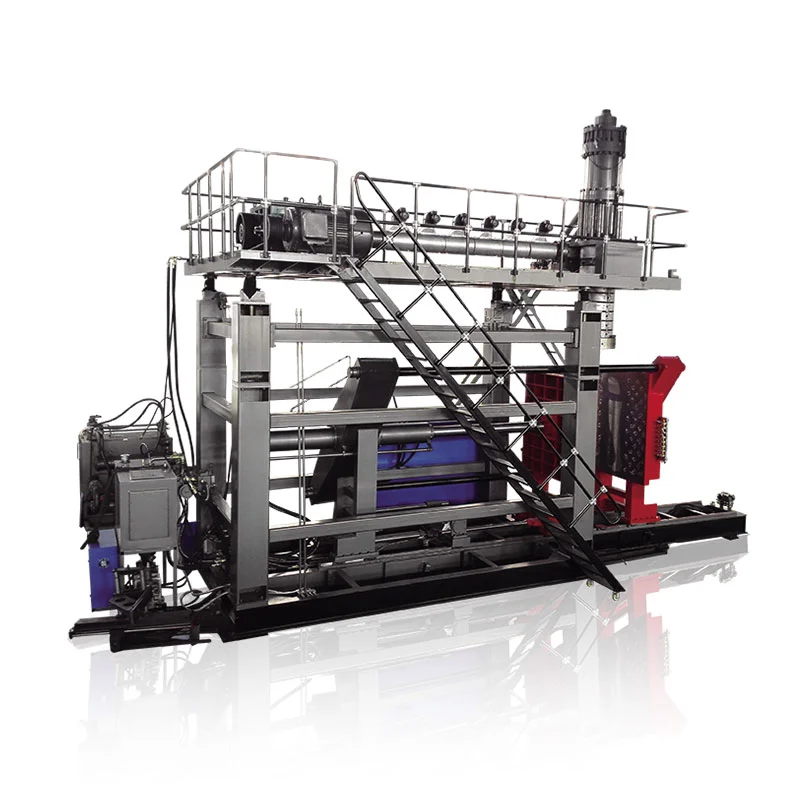
The product is one assembled system
The inner bottle fits the cage, pallet, valve and filling connection.
The head, parison profile, mold and cooling make the approved wall map.
Take-out, trimming, assembly and testing sustain the required accepted output.
The trial links each accepted unit to material, settings, measurements and test results.
KGB1000L-IBC, while its specification table uses KGS1000L-IBC. The dry-cycle row also displays 150 L, which is not a usable rate. This article calls the equipment the Kinggle 1000L IBC platform until the live page and quotation use one confirmed model code and output unit.
Define what the 1000L IBC blow molding machine supplies
The blow molding machine makes the plastic body. In IBC terminology, that body is often called the inner bottle, inner container, liner or inner receptacle. Search language varies by market. The technical agreement should use one controlled term.
A complete composite IBC contains more than that molded body. The outer structure may include a metal cage and a pallet. Closures, gaskets, a bottom discharge valve, labels and identification marks complete the package. Assembly equipment and test stations may sit outside the molding cell.
The distinction has a practical effect. The machine supplier can prove the molding process and the dimensions included in the agreed trial. The complete IBC owner must prove that all supplied components work together. If the cage, pallet or valve comes from another supplier, the buyer needs interface control across companies.
Current United States rules provide a clear example. 49 CFR 178.707 describes a composite IBC as a rigid outer packaging enclosing a plastic inner receptacle. It says the inner receptacle and outer packaging form an integral package. It also says the inner receptacle is not intended to perform its containment function without the outer packaging.
That rule is market-specific, but the engineering lesson travels well. Do not accept the inner bottle in isolation if the commercial product is an assembled IBC. Bring the production cage, pallet, top closure, valve and gaskets into the qualification plan.
The quotation should state the machine-supplier boundary. Name the supplied mold, robot, deflashing, leak tester, conveyors and assembly tooling. Mark all buyer-supplied components and services. A colored boundary drawing is more useful than a long list of “standard accessories.”
Control the inner bottle, cage, pallet and valve on one drawing
The inner bottle drawing should not stop at its outer dimensions. It must show how the bottle meets the rest of the IBC. Build one interface control drawing with references to the approved component drawings.
Start at the top. Record the filling opening, thread or closure interface, sealing face, cap clearance and cage access. Add the top surface height relative to the cage. A closure can meet its own gauge yet become difficult to install when the inner bottle sits too high or too low.
Move to the bottom outlet. Show the outlet centerline, angle, support, valve connection and clearance through the cage. Include the pallet relationship. The warm bottle may change shape during cooling, so measure the interface after the agreed conditioning period.
Map the cage contacts. Mark corner radii, panel zones and any local supports. Contact may change when the filled unit is handled or stacked. The inner bottle should sit where the design expects it to sit. It should not rely on an accidental bulge for support.
| Interface | Controlled evidence | Machine or mold decision |
|---|---|---|
| Top opening and closure | Finish drawing, sealing face, gauge and cap clearance | Neck tooling, blow arrangement, cooling and trim |
| Bottom outlet and valve | Centerline, angle, support, gasket and cage access | Mold insert, local wall profile, cooling and finishing |
| Outer cage | Internal envelope, rail locations and bottle contact zones | Bottle geometry, wall map and release condition |
| Pallet or base | Locator geometry, support surface and handling clearance | Base mold shape, take-out support and post-cooling fixture |
| Label and marking areas | Flatness, position and required identification | Mold surface, wall profile and downstream handling |
Number each interface. Use the same numbers in the mold drawing, inspection plan and factory trial report. When one dimension fails, the team can trace it to tooling, cooling, removal or assembly without arguing about which drawing controls.
Kinggle's sales process asks for product photos, drawings, weight, size, material, thickness, output and chemical resistance. For an IBC project, add the cage, pallet, valve and closure drawings to that package.
Read the published 1000L machine envelope without over-reading it
Kinggle's 1000L IBC product page provides the comparison envelope. It lists a 1000 L maximum container class, a 55 t machine and a 9.5 by 5.1 by 6.5 m machine size. The final layout still needs access, maintenance and auxiliary space.
The public clamping table lists 1000 kN, a 1800 by 1600 mm platen and a maximum mold size of 1600 by 1500 mm. It gives a mold-thickness range of 1200 to 1400 mm. These figures support an early mold-fit review. They do not replace the complete mold assembly drawing.
The extrusion section lists two 100 mm screws with 32 L/D ratios. Published HDPE melting capacity is 180 kg/h per screw. The die-head section lists a 45 L accumulator and a 33 kg PE accumulator-weight reference.
| Published item | Website value | Required project check |
|---|---|---|
| Container class | 1000 L | Approved inner bottle, gross shot, mold and removal path |
| Machine size and weight | 9.5 x 5.1 x 6.5 m; 55 t | Final GA drawing, foundation, transport split and lifting plan |
| Clamping force | 1000 kN | Projected area, blow pressure, pinch-off and margin |
| Maximum mold size | 1600 x 1500 mm | Full mold, manifolds, hoses, moving parts and robot clearance |
| Mold thickness | 1200 to 1400 mm | Closed stack and platen interface |
| Screws | 100 mm x 2; 32 L/D | Layer structure, resin grades and actual ordered melt path |
| Published HDPE melt capacity | 180 kg/h x 2 | Stable recovery with the approved formulation |
| Accumulator references | 45 L; 33 kg PE | Gross parison mass, reserve, resin basis and profile |
| Blow air | 0.8 MPa; 2 m³/min | Peak flow, receiver, air quality and pressure at the machine |
| Cooling water | 0.3 MPa; 120 L/min | Temperature, heat load, water quality and circuit balance |
| Published power reference | 110 to 150 kW average | Measurement boundary, product, settings and accepted output |
The page's dry-cycle row currently shows 150 L. Litres are not a cycle rate. Do not turn that row into 150 pieces per hour or another output claim. Ask Kinggle to confirm the intended number and unit in the quotation.
Each row answers one narrow question. A maximum mold width does not prove robot clearance. An accumulator mass does not prove the finished inner bottle weight. A melt-capacity figure does not equal accepted output. Connect the rows through the approved product and trial plan.
Ask for the connected-load schedule as well. Motor and heater rows describe major components, but the final installed load may also include controls, pumps, robot, material handling and ordered auxiliaries.
Build the accumulator decision from a measured mass balance
The finished inner bottle is only part of each shot. The parison also forms top flash, bottom tails, outlet trim and other process scrap. The accumulator must supply the whole parison under the approved material basis.
Weigh a known production sample if one exists. Remove closures, valves and any separately assembled parts. Then weigh or estimate each trim stream. Keep the estimate tied to the proposed mold and pinch design.
finished inner receptacle + top flash + bottom tails + outlet trim + other molded scrap
Compare this result with the published 33 kg PE accumulator-weight reference. Do not compare finished weight alone. The project also needs operating reserve. The selected resin, color and layer arrangement may change the useful mass basis.
Volume creates another check. The page lists a 45 L accumulator. The relation between volume and mass depends on the actual melt and the manufacturer's definition. Do not convert 45 L directly into a finished-product weight without the supplier's calculation.
Accumulator discharge time matters because a long, heavy parison can sag. The head must deliver the programmed parison before gravity changes the wall distribution beyond control. Record the discharge window, melt condition and die-gap profile during the trial.
Recovery also matters. The two extruders must prepare the next shot inside the production cycle. Compare measured recovery time with cooling and downstream work. A high catalog melt rate cannot help if the approved material system recovers slowly or the downstream cell is already full.
Use the mass record with Kinggle's parison programming guide. Mass tells you how much material entered the mold. The wall map shows where that material went.
Give every layer a written job before ordering two extruders
The product page describes multi-layer production and lists two extruders. That is evidence of a multi-stream platform. It is not a complete layer specification.
Write the function of each layer. One layer may provide the controlled contact surface. Another may carry approved in-process regrind. Color or UV protection may sit in a defined stream. The exact design depends on the product, contents, market and approved test program.
Then define the permitted materials. Name resin grades, masterbatch, additives and regrind source. Record whether regrind comes only from the same manufacturing process. Do not use the word “recycled” as a substitute for a controlled material specification.
Current United States requirements illustrate why this matters. Section 178.707 requires known plastic specifications for composite IBC inner receptacles. It also restricts used material unless approved, while allowing production residues or regrind from the same manufacturing process under the stated conditions. Other markets may apply different rules.
Layer ratio needs a target and a working range. State how the ratio will be set and checked. Gravimetric feed records, extruder output checks or destructive section analysis may support the control plan. Choose the method before the factory trial.
The head drawing should show the melt path. Identify which extruder feeds each layer. Record the number of passages and the order at the die. Add purge and material-change procedures. If the project will run both single-layer and multi-layer products, define the conversion procedure and its acceptance check.
Machine description
Two published 100 mm screws and a multi-layer statement show the platform direction. They do not define the ordered layer functions or ratios.
Project specification
A layer diagram names each material stream, function, target ratio, allowed range, verification method and change-control rule.
Do not promise lower cost or longer life from multi-layer construction without the approved formula and test evidence. Those outcomes depend on the selected materials, distribution and finished IBC design.
Check the mold, clamp and parison path as one mechanical system
A 1000L mold occupies more than a catalog width and height. It includes cooling manifolds, hoses, neck tooling, outlet inserts, pinch areas, lifting points and any moving details. The robot and hot inner bottle need a clear removal path.
Overlay the complete mold drawing on the platen drawing. Check tie rods, clamping centerline, blow hardware and service connections. Review the closed thickness and opening sequence. A mold can fit between the platens and still block a hose or robot movement.
Clamp selection should use projected area and blowing pressure. The published 1000 kN is a machine-page reference. Ask for the project calculation. Include pinch-off forces and a stated margin. Large flat panels can produce a demanding projected area even when the inner bottle is light for its volume.
The parison path needs equal attention. Confirm the die centerline, discharge length, mold capture and closing sequence. A long parison can swing or stretch before capture. The profile must account for shoulder, corners, outlet zone and base.
Pinch areas need enough material to weld, yet excess material increases trim and cooling. The outlet insert needs local control. The top opening needs stable geometry for its closure. These features belong on the numbered wall map.
Venting and surface finish affect release and appearance. The cage may hide some panels, but it cannot repair a molded defect. Review every contact and label area that remains functional after assembly.
Kinggle's mold design guide covers fit, pinch-off, venting and cooling. Use it with the final assembly drawing, not as a generic mold checklist.
Approve the mold only after the machine supplier, mold builder, cage supplier and IBC owner agree on interfaces. Record each approved drawing revision in the purchase file.
Protect IBC geometry through cooling, removal and conditioning
Large surfaces continue to move after the mold opens. The inner bottle may look acceptable at release and drift while it cools. That movement can change the closure height, valve position or cage contact.
Design cooling circuits around thermal zones. Shoulders, corners, necks, outlet inserts and base supports may need different flow. Name each circuit on the mold drawing. Add target inlet temperature and flow. A single pressure reading cannot prove balanced cooling.
Measure supply and return conditions during the trial. Inspect flow at each circuit where the system permits. Record mold temperature at agreed locations. If one zone remains hot, do not hide it by extending the whole cycle without investigating the circuit.
Take-out support is part of cooling. Define where the robot grips and where the bottle lands. A warm panel can deform under a narrow gripper or conveyor rail. The bottom outlet must avoid impact. The base should remain supported while the part reaches handling strength.
Set a conditioning time before dimensional checks. State the ambient condition when it matters. Use the same timing for trial samples and production inspection. Measuring one bottle hot and another cold creates noise that looks like process drift.
The product page lists 0.3 MPa and 120 L/min as cooling-water references. These figures help plan the connection. They do not specify the water temperature or total heat-removal capacity. Ask for the machine and mold heat loads.
Track cooling time against quality. Kinggle's cycle-time guide separates cooling, recovery and handling. The useful target is the shortest stable cycle that meets the dimensional and functional plan.
Prove the molded bottle against production cage, pallet and valve parts
Use production-intent components during qualification. Prototype cages or hand-modified pallets can hide interface errors. Record the supplier, part number and revision for each assembly component.
Begin with a dry fit. Place the conditioned inner bottle in the cage and pallet. Check locator contact, panel clearance, top opening access and outlet position. Install the valve and top closure with the defined tools and torque method where applicable.
Measure the assembled unit at the interfaces. Do not repeat every molded dimension. Focus on what controls filling, discharge, handling, stacking and test preparation. Use go or no-go gauges where they reduce operator judgment.
Inspect contact after handling. Lift or move the unit with the approved method. Look for new marks, local pressure points or movement. The inner bottle and cage should work as the design intends, not merely fit while stationary.
| Assembly check | What to record | Possible process connection |
|---|---|---|
| Cage insertion | Clearance, interference, orientation and insertion method | Body dimensions, cooling, take-out deformation |
| Pallet seating | Support contact, rocking, locator fit and outlet height | Base shape, cooling support and mold insert |
| Top closure | Gauge result, sealing face and installed height | Neck tooling, trim, shrinkage and handling |
| Bottom valve | Centerline, angle, gasket condition and cage access | Outlet insert, wall distribution and finishing |
| Completed unit | Identification, visual condition and traceable component revisions | Assembly controls and final inspection |
Leak testing should use an approved setup. Define which components are installed, the test medium, pressure or vacuum, stabilization, duration and reject rule. The method must match the applicable product program. A quick shop-floor check does not automatically replace a formal test.
Retain one approved assembly as a boundary sample. Photograph the interfaces. Store the molded recipe, material lot, cage revision, pallet revision, valve and closure data with the sample record.
Separate the machine FAT from complete IBC design-type approval
The factory acceptance test proves the ordered molding cell against the agreed product and conditions. It does not grant approval for every assembled IBC, filling substance or market.
The UNECE UN Model Regulations Rev. 24 is the current 2025 global reference publication. Its Chapter 6.5 addresses IBC construction and testing. National and modal rules may adopt a specific edition or add requirements. Confirm the applicable authority and qualified test route before freezing the validation plan.
Do not start with a single drop height found online. The design type, material, intended contents, packing group, preparation, conditioning, closures and complete test sequence affect the program. The competent authority or qualified laboratory should define the required evidence.
Machine qualification should still create useful upstream evidence. Record material specifications, layer arrangement, gross and net mass, wall map, dimensions, leak result, recipe and component revisions. Retain samples from the tested lot. This information helps link the manufacturing process to later package testing.
Separate three documents. The machine FAT report covers build and process performance. The assembly qualification report covers cage, pallet, valve and closure fit. The regulatory test report covers the applicable design type. Each report should state its scope and limitations.
Production controls continue after approval. Manage changes to resin, pigment, inhibitor, regrind, layer ratio, mold, closure, valve, cage and pallet through the approved quality system. A small change can affect the basis used for testing.
For a smaller regulated packaging line, the KGB200L/LP chemical drum cell guide shows the same distinction between machine evidence and package approval.
Measure output at the last accepted cell gate
The current product page does not provide a usable production rate. Its dry-cycle row displays 150 L, so this article does not infer pieces per hour. The project needs an accepted output target based on the real inner bottle and complete cell.
Choose the output boundary first. Molded inner bottles per hour measures the molding cell. Assembled and leak-tested IBCs per hour measures a larger system. Both numbers can be useful, but they should not share one label.
inner bottles passing the agreed molding inspection ÷ observed minutes x 60
assembled units passing the agreed final gate ÷ observed minutes x 60
Count all starts, rejects and stops. Classify the causes. Extrusion recovery, cooling, robot handling, trim, cage insertion, valve installation and leak testing can each set the cell rate. The slowest stable gate determines finished output.
Material demand should use gross shot mass and molding events. The finished inner bottle weight misses trim and startup losses. Report gross kilograms per accepted bottle as well as pieces per hour.
Energy needs the same boundary. Kinggle publishes 110 to 150 kW as an average power reference for the platform. It is not kWh per IBC. Record the selected measurement point, production state, run duration and accepted count. The energy measurement guide explains that distinction.
Use a long enough trial to expose recovery and downstream queues. A short burst can show the machine's motion but miss material drift, cooling imbalance or cage accumulation.
A useful dashboard includes accepted molded bottles, accepted complete IBCs, first-pass yield, gross kilograms per accepted bottle, trim mass, average cycle, counted downtime and energy per accepted unit. Define each term in the acceptance protocol.
Plan the building around the current general arrangement drawing
A 55 t machine needs more than floor area. The building must support installation, maintenance, material movement and safe access. Begin with the supplier's current general arrangement drawing for the ordered revision.
The public table lists a 9.5 by 5.1 by 6.5 m machine. The product-page drawing displays its own dimensions. Treat the drawing as a visual reference until Kinggle confirms which drawing revision matches the quotation. Do not use a web image to design the foundation.
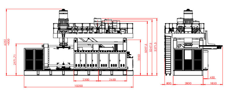
Mark the mold route. Include door size, floor capacity, crane hook height, lifting points and storage. Show the screw pull space and access to the accumulator head. Add safe stairs and platform access around elevated equipment.
Map material flow from storage to each extruder. Add masterbatch, regrind, conveying, grinding and dust control. Keep clean trim separate from mixed waste. Show how a full hopper or blocked return line will be serviced.
Use project-specific utility sheets. The page lists 0.8 MPa and 2 m³/min for blow air. It lists 0.3 MPa and 120 L/min for cooling water. Plan pressure at the machine, peak flow, receivers, treatment, supply temperature, return condition and heat rejection.
Electrical design needs connected load, voltage, frequency, protection, cable routes and auxiliary loads. The published 110 to 150 kW average reference is not the connected load. Include chillers, compressors, material equipment, grinder, assembly and test stations in the plant total.
Use Kinggle's utility requirements guide to build the boundary sheet. Freeze that sheet with the layout and foundation drawing.
Follow one traceable IBC lot through the factory acceptance test
A useful FAT begins before the machine runs. Agree the inner bottle drawing, component revisions, resin, layer structure, wall map, sample plan, output boundary and acceptance limits. Name the instruments and test methods.
- Confirm the ordered platform. Check the final model code, extruders, accumulator head, clamping arrangement, controller, robot, blow hardware, guarding and auxiliaries against the contract.
- Confirm utilities and calibration. Record power, air and cooling conditions. List the measuring instruments and calibration status.
- Load controlled materials. Record each resin grade, lot, color, additive and regrind stream. Verify the feed route to each extruder.
- Stabilize the molding process. Reach repeatable recovery, discharge, mold cooling, removal and trim before the formal run begins.
- Freeze the starting recipe. Save temperatures, speeds, layer settings, parison profile, timings, pressures and downstream settings under one revision.
- Run the agreed production window. Count starts, accepted bottles, rejects and every stop. Keep reason codes specific.
- Measure the molded plan. Check net and gross mass, trim, wall map, openings, outlet, base, body geometry, appearance and leak result.
- Assemble production components. Fit the approved cage, pallet, top closure, valve and gaskets. Complete the interface gauges and assembly checks.
- Close the evidence package. Retain labeled samples, export the final recipe and record every open deviation with an owner and retest method.
Select samples from the start, middle and end of the formal run. Label them with time and recipe revision. Keep the cage, pallet, valve and closure revisions with the sample record.
Use the actual downstream stations when possible. A hand-trimmed sample may pass while the production trim fixture damages the outlet. A lab leak test may hide a queue at the planned line tester.
Do not mix regulatory approval into a general FAT signature. If a formal test is witnessed, attach the separate test protocol and report. State the design type, sample preparation and authority.
Photograph the machine nameplate, mold identification and retained samples. Save the alarm history and production counter at the end of the run. Record any manual intervention that changed a bottle, even when the final inspection passed. These details help the site team reproduce the accepted state after installation.
Kinggle's sales process includes inspection and an invitation to join the test. Use the machine FAT guide to define the record. Review available equipment footage on Kinggle's video page before the visit so the team can prepare focused questions.
Send a quotation-ready IBC project file instead of a volume alone
A request that says only “1000L IBC machine” leaves the important work undefined. Send an approved inner bottle drawing and photos. Add a physical sample when practical. State the nominal capacity and intended contents.
Include net molded weight, gross shot estimate, trim map and wall-thickness map. Name each resin stream, additive, color and regrind rule. Attach the layer diagram and verification method.
Add the cage, pallet, top closure, bottom valve and gasket drawings. Mark the controlled interfaces. State who supplies each component during mold trial, FAT and site startup.
List all product checks. Include dimensions, gauges, conditioning time, leak method and assembly checks. Identify any applicable design-type program, competent authority or test laboratory. Do not paste a generic test list from another market.
Define accepted output at the correct gate. State the planned shift pattern and annual demand. Describe robot take-out, trimming, cooling support, cage insertion, closure and valve assembly, leak testing, marking and pallet flow.
Provide factory voltage, frequency, available air and cooling, ambient conditions, altitude, floor plan, crane data and access route. Ask for the final general arrangement, foundation loads, utility sheet and transport split.
The supplier response should name the final machine model and revision. It should include the extruder and head architecture, accumulator basis, mold envelope, clamp review, auxiliary boundary, acceptance protocol and data handover.
Use Kinggle's download center for current documents. Send the controlled project file through the contact page. The quotation can then answer the actual IBC project instead of a broad 1000L label.
Frequently asked questions
These answers address the machine-selection issues that most often change the scope, trial or factory plan. Published model data remains a starting reference. The signed technical agreement should control the ordered system.
What does a 1000L IBC blow molding machine actually make?
It forms the plastic inner receptacle, also called the inner bottle or liner. The complete composite IBC also includes its outer cage or packaging, pallet, top closure, bottom valve, gaskets and other service or structural parts.
What is the model number of Kinggle's 1000L IBC machine?
The current English page is inconsistent. Its product summary shows KGB1000L-IBC, while the specification table shows KGS1000L-IBC. Confirm the final model code and revision in the quotation, drawings, nameplate and manuals.
Does the published 33 kg accumulator value mean a 33 kg finished bottle?
No. The page labels 33 kg as the PE accumulator-weight reference. Gross parison mass includes the finished inner receptacle and all molded trim. Confirm resin basis, reserve, layer structure and the complete shot calculation.
What is the production output of the Kinggle 1000L IBC platform?
The current dry-cycle row displays 150 L, which is not a usable production-rate unit. Do not infer pieces per hour. Define accepted molded bottles or accepted complete IBCs per hour and prove that rate during the agreed production trial.
Why must the cage and pallet be present during the machine trial?
The bottle must fit and function inside the complete assembly. Production cages, pallets, closures and valves expose errors in height, outlet position, support, clearance and handling that an isolated bottle inspection can miss.
What information should I send for a 1000L IBC machine quotation?
Send the inner bottle drawing, sample, weight, wall map, materials, layer design and trim estimate. Add the cage, pallet, closure and valve drawings, tests, output target, downstream scope, factory layout and utility conditions.
Build the machine proposal around the complete IBC
Send Kinggle the controlled inner bottle file, component interfaces, material and layer plan, output target, tests and factory utilities. The engineering team can then confirm the 1000L platform, mold, auxiliaries and acceptance scope.
Request a 1000L IBC machine solution