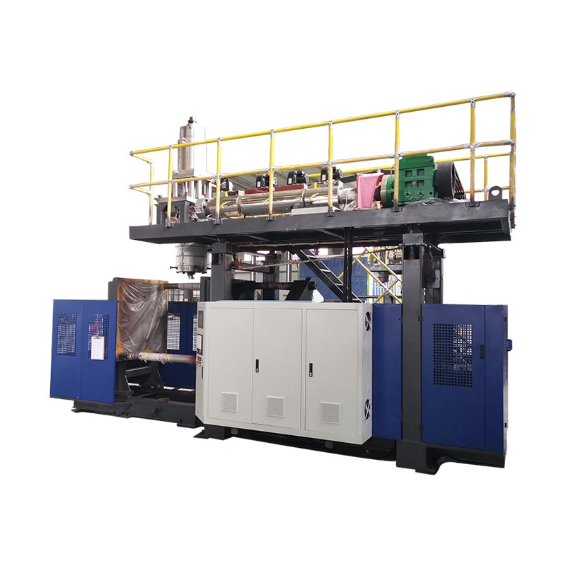
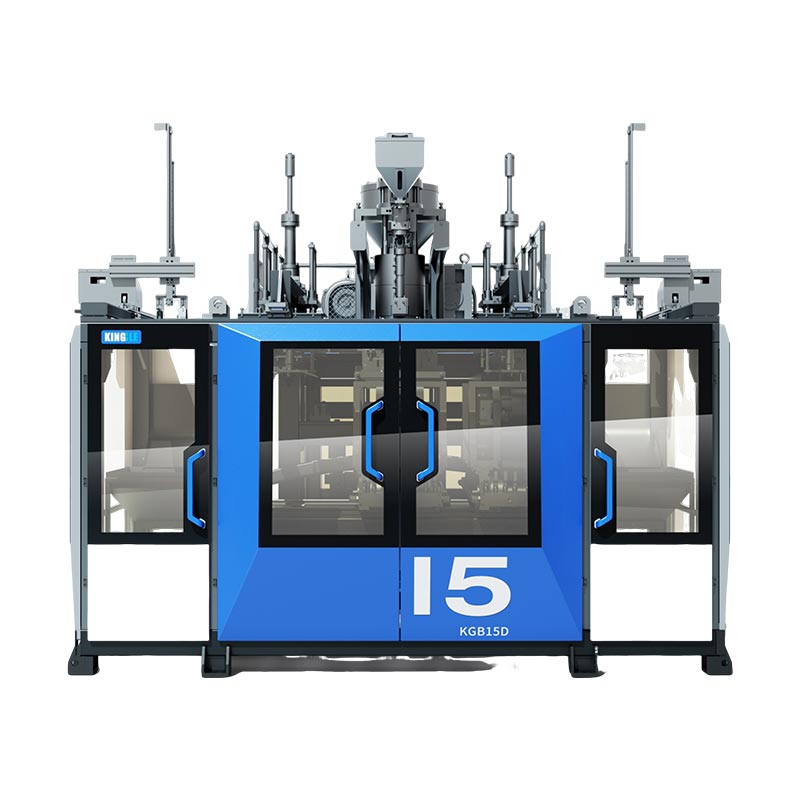
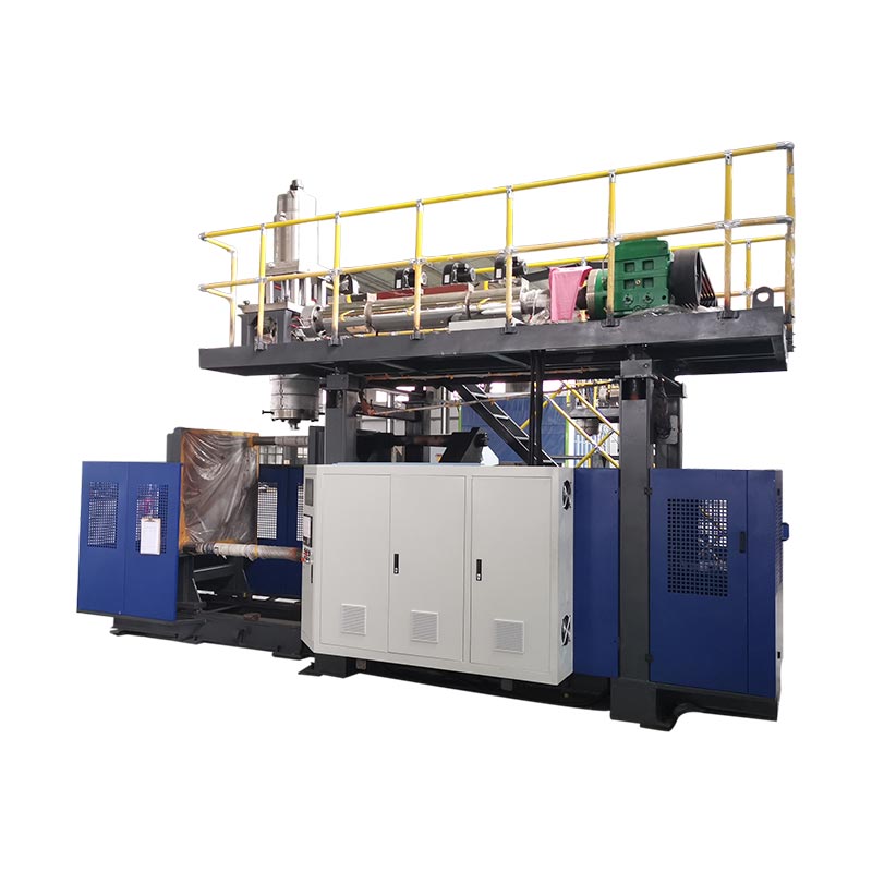
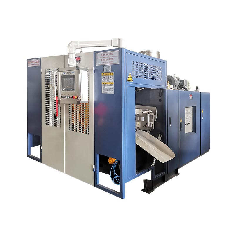
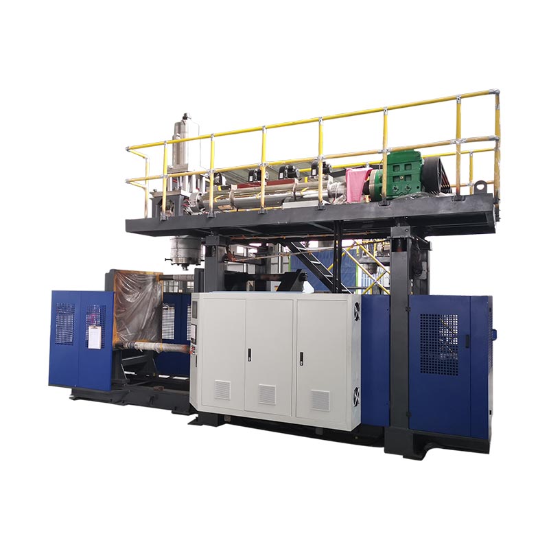
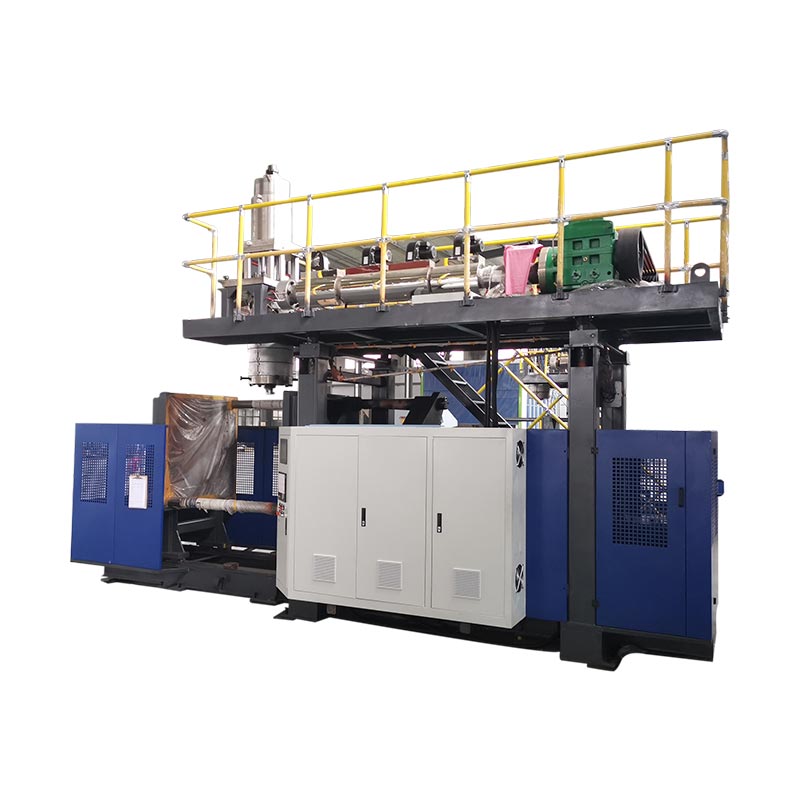
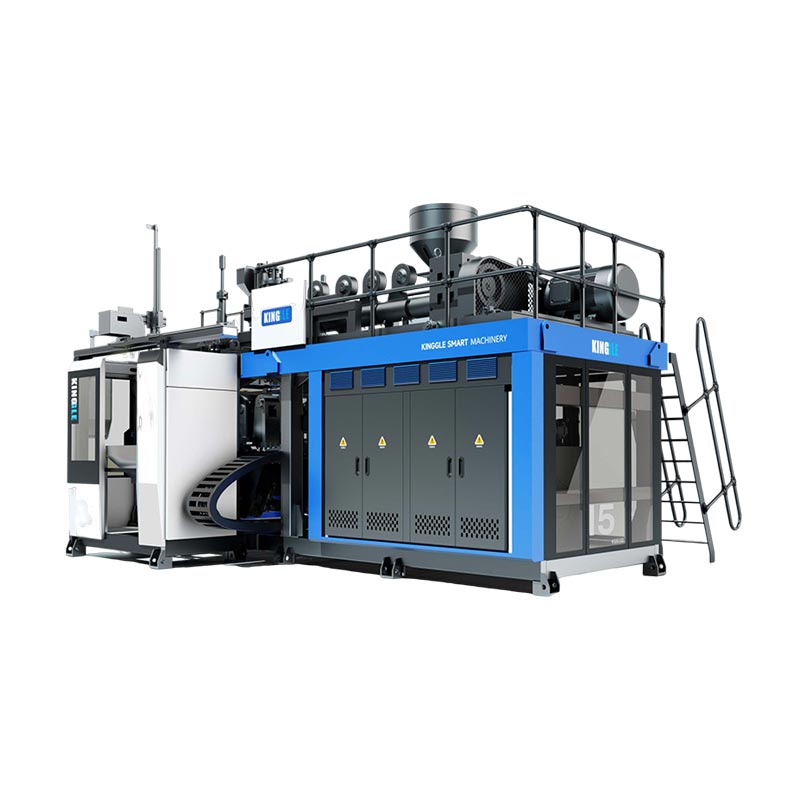
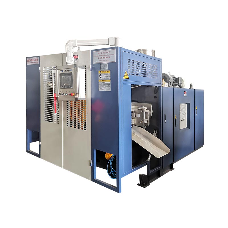
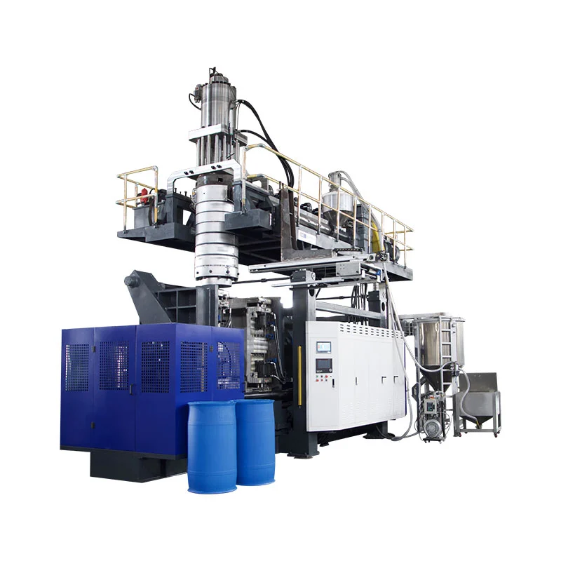
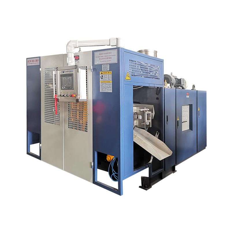
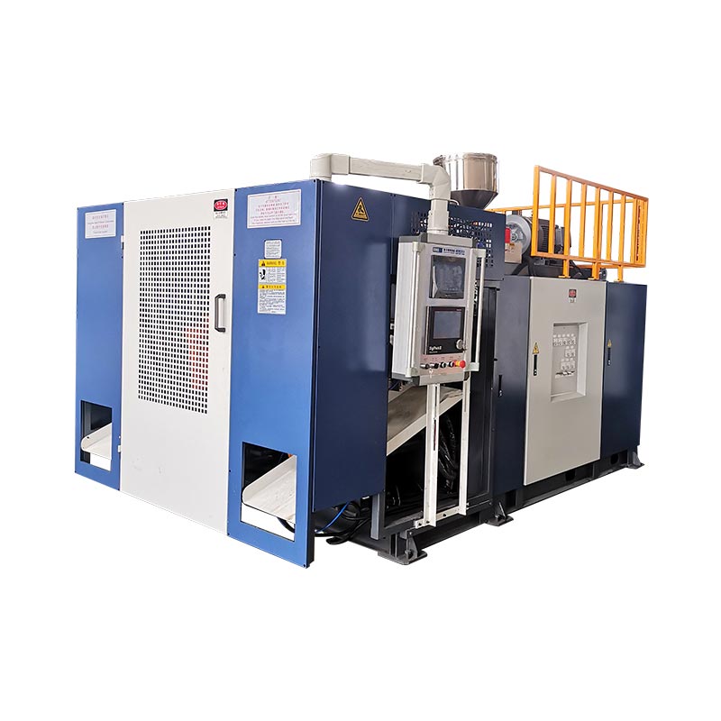
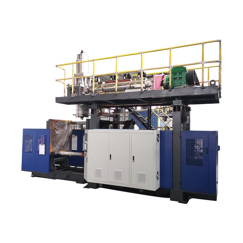
A second station changes how the machine uses extrusion, cooling and mold-handling time. It does not automatically double sellable output, lower energy per bottle or make a larger product. Three paired Kinggle machine sizes show where the real differences appear.
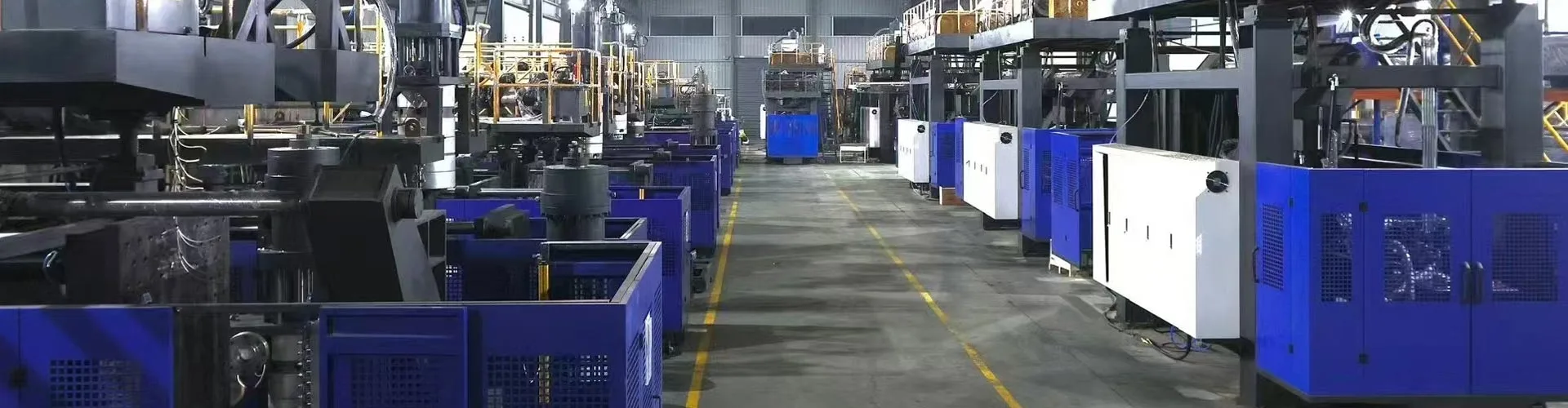
The real single vs double station blow molding machine comparison is therefore a complete-cell study, not a carriage count. The decision must connect the bottle, production schedule, gross melt demand, two-station sequence and accepted-part requirement.
What changes between one station and two?
In a single-station continuous extrusion blow molding machine, one mold-and-clamp position captures the parison, forms the part, cools it and releases it. The next molding event must fit around that one station's sequence.
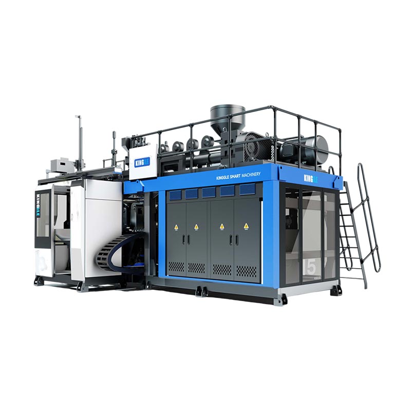
A double-station—or twin-station—extrusion blow molding machine alternates two mold positions around a shared extrusion system. One station can be in a blowing, cooling or part-removal step while the other prepares to capture the next parison. This is why double-station equipment is also described as a double-sided or shuttle blow molding machine in some markets.
This simplified sequence explains the opportunity, not the final production rate. Station travel, parison formation, mold close, blowing, exhaust, cooling, ejection, trimming and downstream transfer still have to fit together. Independent shuttle-machine literature also lists single- and double-sided configurations separately from single- and multi-parison die heads, reinforcing that these are different equipment choices.
Do not confuse station count, head count, cavity count and layer count
Many quotation mistakes begin because “double” is used without saying what is doubled. A double-station machine is not necessarily a double-head machine, a two-cavity mold or a two-layer line.
| Term | What it counts | What it changes | Question for the supplier |
|---|---|---|---|
| Single or double station | Mold-and-clamp positions that work in sequence | Machine sequence, mold-set requirement, output potential, footprint and handling | How many complete mold stations alternate on this machine? |
| Single or multi-head die | Parisons extruded at one molding event | How many mold cavities can be fed at once and the required outlet pitch | How many outlets are included, and what is their center distance? |
| Single or multi-cavity mold | Parts formed in one mold close | Parts per molding event, mold size, cooling balance and trimming | How many saleable parts should one mold event produce? |
| Single or multilayer | Material layers in the part wall | Extruders, die-head architecture, material handling and process control | Which materials and layer structure are included in the quotation? |
The R&B continuous extrusion shuttle data sheet, for example, lists single- and multi-parison die heads separately from one- or two-station clamp configurations. Multi-parison tooling is one output lever; a second mold station is another. A proposal may use either lever or combine both, so the quotation must identify each separately.
Terminology also changes by region. Buyers may search for a double station blow molding machine, twin station blow moulding machine, two-station bottle blowing machine or double-sided shuttle blow molder. Confirm the physical sequence rather than selecting by name alone.
Original comparison: three paired Kinggle machine sizes
The following analysis uses specifications published on six current Kinggle product pages. Each pair has the same nominal maximum container capacity, which makes the station difference easier to see. The figures are catalogue references, not a production guarantee for every bottle, resin, die head or option package.
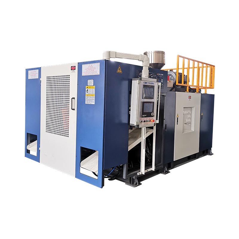
| Capacity and model | Stations | Published output label | HDPE melting capacity | Machine dimensions (L×W×H) | Simple L×W envelope* | Weight | Clamping force |
|---|---|---|---|---|---|---|---|
| 2L KGB2L | Single | 600 pcs/h dry cycle | 30 kg/h | 3.1 × 1.7 × 2.5 m | 5.3 m² | 2.5 t | 40 kN |
| 2L KGB2D | Double | 600 × 2 pcs/h dry cycle | 55 kg/h | 3.1 × 2.2 × 2.5 m | 6.8 m² | 4.5 t | 40 kN |
| 5L KGB5L | Single | 500 pcs/h dry cycle | 55 kg/h | 3.1 × 2.2 × 2.5 m | 6.8 m² | 3.0 t | 65 kN |
| 5L KGB5D | Double | 500 × 2 pcs/h dry cycle | 80 kg/h | 3.2 × 2.2 × 2.5 m | 7.0 m² | 5.2 t | 65 kN |
| 15L KGB15L | Single | 450 pcs/h dry cycle | 100 kg/h | 4.5 × 2.2 × 2.8 m | 9.9 m² | 7.5 t | 165 kN |
| 15L KGB15D | Double | 450 × 2 pcs/h dry cycle | 120 kg/h | 4.8 × 2.9 × 2.8 m | 13.9 m² | 12.5 t | 165 kN |
What the paired data reveals
1. Station count does not define maximum part size
Within each Kinggle pair, nominal container capacity and published clamping force remain the same: 2L and 40 kN, 5L and 65 kN, or 15L and 165 kN. The second station changes the production sequence; it does not turn a 5L platform into a 15L platform.
This distinction matters during machine selection. Part volume, projected area, mold dimensions and required clamp still have to fit the platform. Kinggle's blow molding machine selection guide starts from the container before choosing station count.
2. The double-station pairs add melt capacity, but not by one fixed ratio
The published HDPE melting capacity rises from 30 to 55 kg/h in the 2L pair, from 55 to 80 kg/h in the 5L pair, and from 100 to 120 kg/h in the 15L pair. Those increases are not identical and should not be converted into a universal “double station multiplier.”
This is the most important capacity lesson in the data. Two stations can create more molding opportunities, but the extruder still has to supply the gross parison mass. A heavier bottle, more flash, more die outlets or shorter event interval raises melt demand. When extrusion becomes the bottleneck, adding station availability cannot solve it.
3. Weight and installation envelope increase differently by size
Moving from the single to the double model raises published machine weight from 2.5 to 4.5 tonnes at 2L, 3.0 to 5.2 tonnes at 5L, and 7.5 to 12.5 tonnes at 15L. The calculated L×W machine envelope changes from about 5.3 to 6.8 m², 6.8 to 7.0 m², and 9.9 to 13.9 m² respectively.
Floor area is therefore not safely described as “almost the same” or “twice as large.” The result depends on the platform. Neither machine-envelope calculation is a factory layout: service access, material supply, cooling manifolds, control cabinets, part discharge and mold handling still need space. Use Kinggle's power, air, water and layout guide before freezing the site plan.
4. The dry-cycle label is a comparison signal, not a delivery promise
A dry cycle records machine movement without proving the production conditions of a finished part. Actual output has to include parison formation, blow and exhaust time, cooling, ejection, trimming, quality loss and planned stops. A thick 15L jerrycan and a light 500ml bottle cannot be assigned the same output merely because they run on a machine with the same station count.
Calculate output from molding events and mass balance
Start with the product and work backward. Do not begin by multiplying a catalogue number by shift hours.
Step 1: define the required good output
Convert confirmed demand into good parts per hour using scheduled production hours, planned changeovers and the plant's own availability assumptions. Keep demand scenarios separate—base, seasonal peak and future growth—so excess capacity is visible rather than hidden inside one optimistic target.
Step 2: measure one complete molding event
For the proposed mold, record the number of parisons, parts formed, gross parison mass, finished-part mass, flash/regrind route, stable event interval and accepted quality result. A molding event means one mold captures parison material and produces its set of parts.
Good parts/h = molding events/h × parts per event × accepted fraction
Gross melt demand (kg/h) = molding events/h × gross parison mass per event (kg)
The accepted fraction must come from an agreed trial or an honest plant assumption. Gross parison mass includes the material that enters the molding event, not only the finished bottle. If flash is reground, its handling and reintroduction still affect the line.
Step 3: test the bottlenecks as one line
Compare gross melt demand with the proposed extruder under the actual material. Then confirm mold cooling, blow air, part removal, trimming, leak testing, conveying, packing and grinder capacity. The lowest sustainable stage sets the line output.
For broader continuous-machine output logic, see Kinggle's continuous blow molding machine guide. If part weight or wall distribution changes during speed trials, use the parison programming guide and verify the same wall locations at each condition.
Which configuration fits the production plan?
Single station is usually the cleaner shortlist when…
- verified demand fits one mold station with acceptable operating margin;
- product changes are frequent or production runs are short;
- one mold set is preferred for budget, maintenance or validation reasons;
- the part, mold or removal method makes an alternating layout less practical;
- factory space, lifting access or downstream automation is limited;
- the project is entering a market where demand is not yet proven.
Double station deserves a full line study when…
- stable repeat demand exceeds the realistic single-station output;
- two matched mold stations can run a repeatable process;
- the extruder and die head can supply the required gross melt rate;
- cooling leaves useful time for alternating mold work;
- trimming, testing and material handling can accept the increased flow;
- the additional mold, machine and utility scope has a defensible business case.
Neither list replaces a product trial. It prevents a common procurement error: treating the second station as a standalone output accessory. It is a system decision that changes tooling, controls, commissioning and the flow of parts through the factory.
Utilities and downstream equipment can erase the station advantage
A double-station line may send more heat into the mold-cooling system and create molding events closer together. Compressed air has to hold pressure and deliver flow when the line demands it, not just at idle. Cooling water has to reach both mold circuits with stable conditions. Electrical distribution, hydraulic cooling and cabinet environment must match the final build.
Do not calculate plant services from the comparison table. Some current Kinggle web specifications use inconsistent unit typography, and the average energy figures do not describe an identical product test. Request the project-specific utility sheet, electrical drawing and general arrangement drawing for the ordered configuration.
Check every process after mold opening
- Can take-out equipment receive parts from the alternating stations?
- Can trimming handle the actual flash and neck/bottom geometry?
- Can the leak tester inspect every cavity at the required line rate?
- Can conveyors prevent collision, accumulation and part deformation?
- Can the grinder and blender handle flash without destabilizing regrind proportion?
- Can operators reach both stations safely for approved inspection and changeover work?
If faster running creates unstable wall thickness, flash, cooling distortion or repeat alarms, connect the preventive maintenance record with Kinggle's HMI troubleshooting method before hiding a physical bottleneck with recipe changes.
Compare total installed cost, not machine price alone
A buyer searching for a plastic bottle making machine price may receive two quotations that are not equivalent. One can include the second mold set, take-out and leak testing; another can show only the base molding machine. The lower headline price may therefore describe a less complete production cell.
| Cost layer | Single-station question | Double-station question |
|---|---|---|
| Machine platform | Which extruder, clamp, controls and standard auxiliaries are included? | Which additional carriage, clamp, blow and control equipment is included? |
| Molds and die head | Is one complete mold and the correct die outlet package included? | Are two matched mold stations included, and are head count and outlet pitch identical to the tool plan? |
| Factory services | What power, air, water and floor/loading work is required? | Can existing services support the faster event sequence under simultaneous factory demand? |
| Downstream cell | Which take-out, trimming, testing, conveying and grinding steps are manual or automatic? | Can every downstream stage accept parts from alternating stations without accumulation? |
| Changeover and validation | How long does one mold and recipe change take under the buyer's procedure? | How are two stations aligned, qualified and restored after a product change? |
| Operating risk | What output is lost if the single mold station stops? | Can either station be isolated safely, and what happens to the shared extrusion sequence? |
A useful economic comparison uses the same project boundary on both sides. Include the molding machine, molds, die head, auxiliaries, installation, commissioning, training and factory modifications. Then estimate labor, utilities, planned maintenance, changeover loss, quality loss and downtime using the buyer's own operating assumptions.
Cost per good part = total cost over the comparison period ÷ accepted parts produced over the same period
The numerator and denominator must use the same time window and scope. Do not place a double-station capital figure above a single-station dry-cycle output, or compare an automated double line with a base single machine that excludes trimming and testing. If demand cannot use the added output, idle capacity remains a cost. If demand exceeds the single-station capability, missed production and overtime are also costs.
Price is still a valid purchasing constraint, but it belongs after technical fit. Ask Kinggle to identify every included component and every buyer-supplied item so the quotation can be compared line by line.
A better RFQ separates guaranteed conditions from catalogue references
Send the same input sheet to every supplier. Otherwise, two quotations may use different assumptions and still appear comparable.
| RFQ field | Required input | Why it changes the station decision |
|---|---|---|
| Part | Drawing or sample, maximum dimensions, neck/finish, handle, parting line and trimming requirement | Defines mold fit, movement and downstream work |
| Material | Exact resin grade, color, additives, regrind/PCR plan and supplier data | Changes melt behavior, gross throughput and cooling |
| Mass and wall | Finished weight, gross parison/flash estimate, critical wall locations and tolerance | Turns cycle targets into melt demand and quality evidence |
| Demand | Good parts per hour, shift, year and peak season; SKU/changeover plan | Shows whether the second station can be kept productively loaded |
| Tooling | Station count, die outlets, cavities, center distance, mold sets and cooling layout | Prevents “double station” from hiding a different head or cavity assumption |
| Quality | Weight, dimensional, wall, leak, drop, top-load or other agreed tests | Defines good output instead of movement speed |
| Factory | Power standard, air/water conditions, floor and ceiling limits, lifting path and downstream equipment | Tests whether the full double-station cell can be installed and supported |
Record these items during the acceptance trial
- Machine, mold, die head, resin and recipe identity.
- Stable molding-event interval for each station—not one fastest event.
- Gross parison mass, finished-part weight and flash route.
- Accepted parts by cavity and station over the agreed test window.
- Critical wall, dimensional and functional results.
- Actual air, water and electrical conditions under the demonstrated load.
- Alarm, stop and manual-intervention record during the trial.
This record turns “single versus double station” into a decision based on the buyer's product. It also provides the commissioning baseline for future troubleshooting and preventive maintenance.
Frequently asked questions
Which is faster: a single-station or double-station blow molding machine?
A double-station machine has higher output potential because two mold stations alternate around a shared extrusion system. Actual good output still depends on melt capacity, parison count, cooling, part removal, downstream equipment and accepted quality.
Does a double-station blow molding machine double production?
Not automatically. Published dry-cycle figures may show two alternating stations, but sellable output can be limited by gross melt demand, cooling, trimming, testing, stops or rejects. Verify the machine with the actual product and material.
Is a double-station machine the same as a double-head machine?
No. Station count describes mold-and-clamp positions. Head count describes how many parisons are extruded for a molding event. A machine can combine two stations with one or several die outlets.
Can the two stations run different molds?
Do not assume they can run unrelated products efficiently. The stations share extrusion and process conditions, so product mass, parison timing, cooling and downstream work must be compatible. Confirm the exact arrangement during engineering.
Should I choose a single or double station for 5L containers?
Container volume only identifies the platform. Choose station count from verified good-parts demand, product weight, run length, mold and die-head plan, available utilities, factory layout and downstream capacity.
How should blow molding machine output be calculated?
Use molding events per hour multiplied by parts per event and the accepted fraction. Check the result against gross melt demand, cooling and every downstream step. Do not use dry cycle alone as production output.
What information is needed for a single-versus-double-station quotation?
Provide the part drawing, material grade, finished and gross parison mass, wall and quality requirements, good-parts target, SKU plan, mold and cavity concept, utilities, layout and downstream equipment.