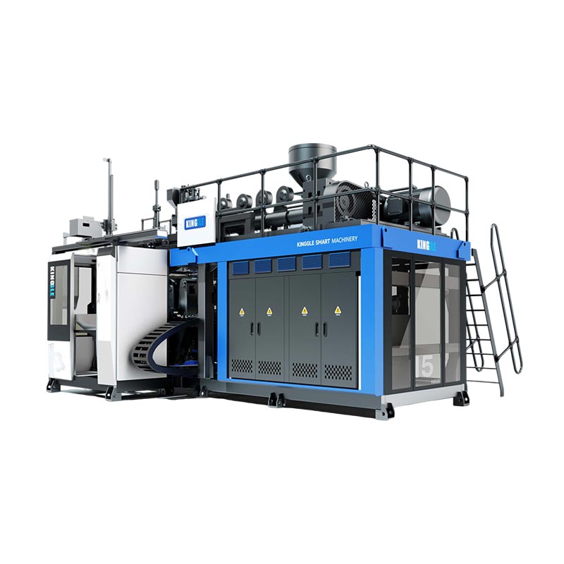
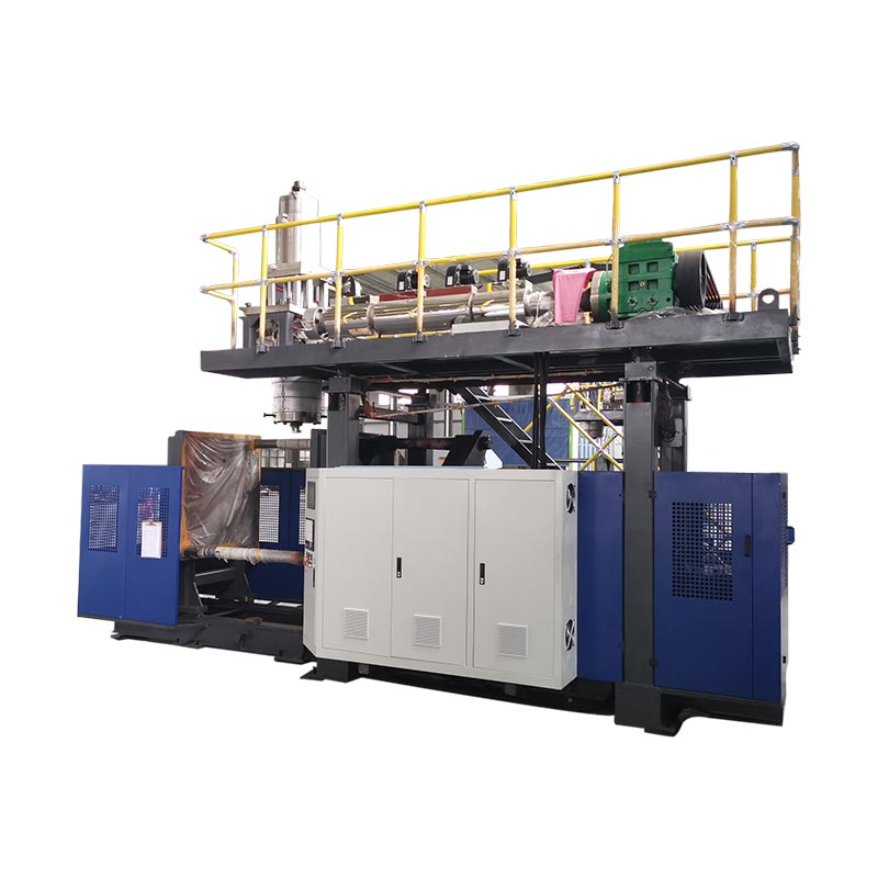
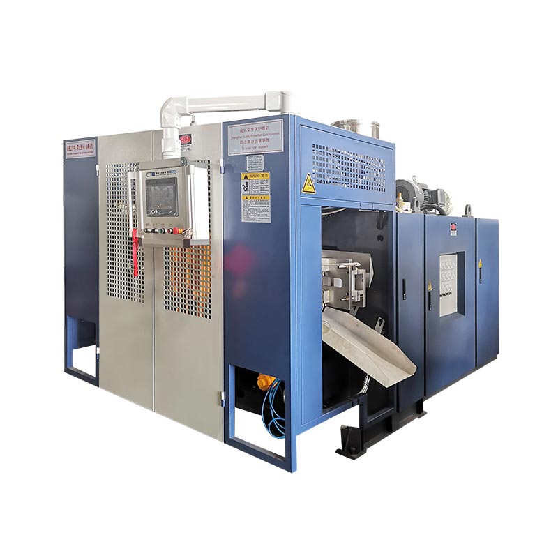
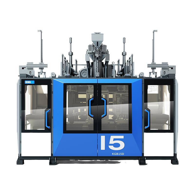
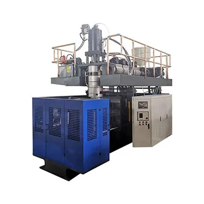
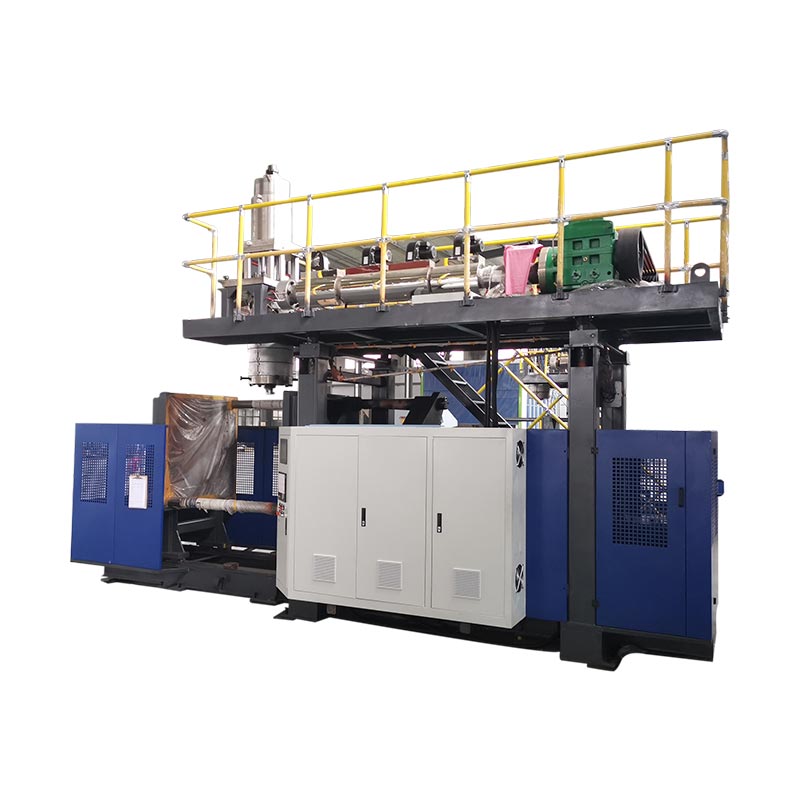
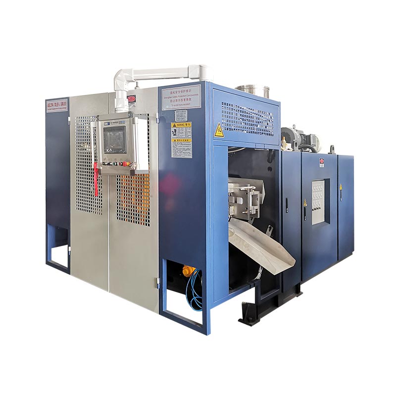
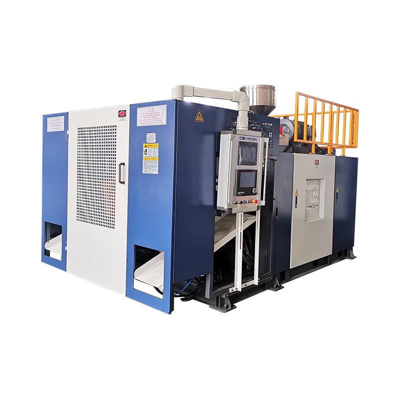
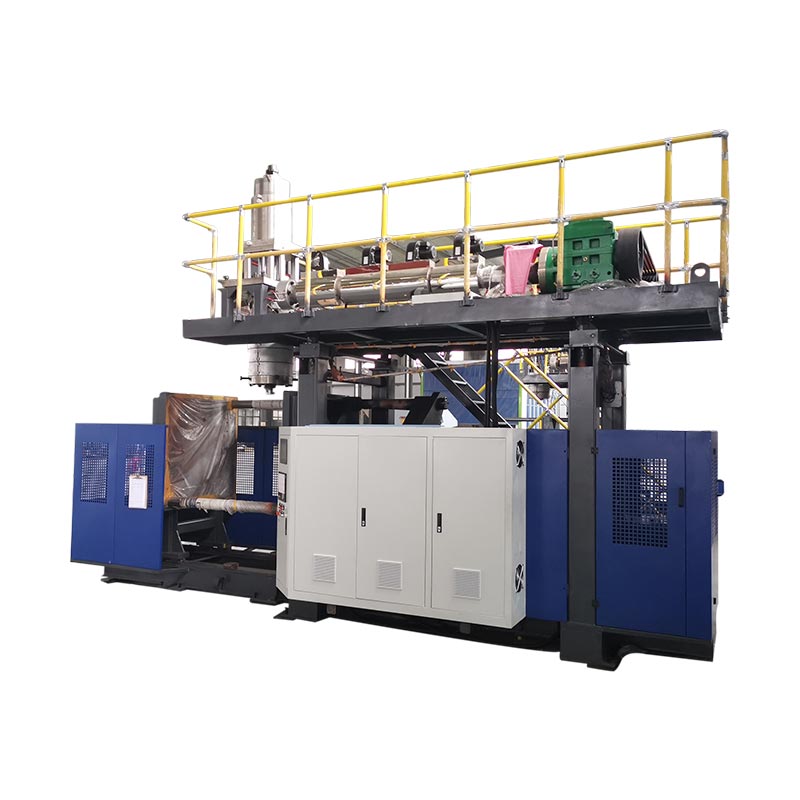
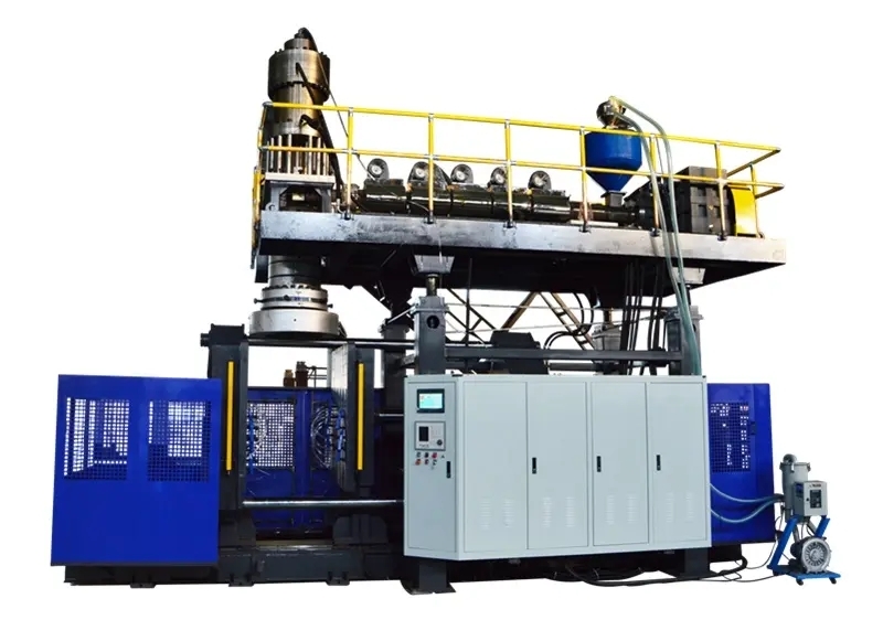
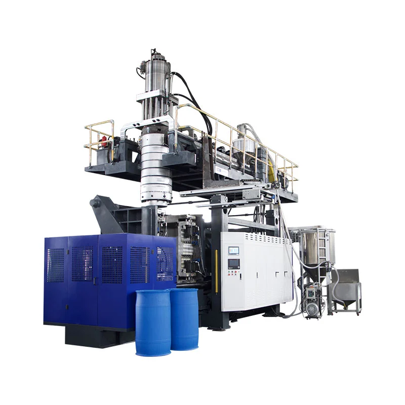
Two heads, two parisons and two cavities often belong in the same production concept—but they are not interchangeable terms. The correct layout starts with the bottle, outlet pitch, mold space and gross melt demand, not a target head count.
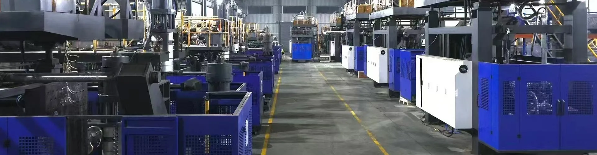
A buyer asking for a “four-cavity bottle blowing machine” may receive a four-outlet die head, a four-cavity mold and one or two mold stations. Another buyer asking for a “double head blow molding machine” may be referring only to two parisons. Unless the quotation lists each element, the two parties can discuss the same number while imagining different equipment.
This guide separates those terms, uses current Kinggle 2L, 5L and 15L specifications to show the dimensional limits behind head selection, and provides a mass-balance method for comparing one-, two-, three- and four-head concepts without inventing production output.
First, name the four different counts
The word head is used loosely in the market. An extrusion blow molding die head distributes melt and forms the tubular parison. A multi-parison die head has several outlets. The mold then closes around those parisons, and each mold cavity forms a part. A station is the complete mold-and-clamp position that receives them. A layer is a material layer created by the extrusion and die-head system.
| Count | Physical meaning | Example buyer question | Do not assume |
|---|---|---|---|
| Die-head outlets | Openings from which parisons emerge at one molding event | Is the proposal single, double, triple or four head? | That an outlet count guarantees the same number of accepted bottles |
| Parisons | Tubular melt lengths captured by the mold | How will weight and timing be balanced between parisons? | That equally spaced outlets always deliver equal parisons |
| Mold cavities | Part shapes formed in one mold close | Does the mold make one, two or four parts per event? | That cavity count describes the number of mold stations |
| Stations | Complete mold-and-clamp positions used by the machine | Is the machine single station or double station? | That a second station is a second die head |
| Layers | Material layers across the wall structure | Is the part monolayer or multilayer? | That “double layer” means double head or double cavity |
Independent equipment literature makes the same distinction. The R&B continuous extrusion shuttle data sheet lists one- or two-station clamp configurations separately from die-head configurations with multiple outlets. That separation is useful in any RFQ: specify stations, die outlets, mold cavities and layers on different lines.
What changes as a die head gains outlets?
A multi-head, multi-die or multi-parison blow molding machine creates several parisons in parallel. If the mold and process are designed to capture each parison and form one bottle, parts per molding event can increase. The gain is conditional. Each outlet needs space, melt flow, temperature control and a corresponding cavity position.
This diagram is conceptual, not a Kinggle tooling drawing. Real outlet diameters, pitch, flow channels and cavity layout depend on the bottle and machine. “Two head,” “three head” and “four head” are therefore starting descriptions rather than complete specifications.
More heads divide the available molding width
A single large parison can use more of the machine's available mold width. When several outlets share that space, bottle width, cavity pitch, neck position, flash pocket and cooling connections have to fit side by side. The mold also needs enough steel between cavities and enough room for trimming and part removal.
More heads increase total melt required per event
If one gross parison weighs 0.10 kg, four equivalent parisons require 0.40 kg per molding event before considering any difference in their actual weights. The example explains the arithmetic only; it is not a Kinggle bottle specification. Shortening the interval between events raises hourly melt demand further.
More heads create more positions to control
Four visible bottles after mold opening do not prove four equivalent processes. One outlet can run warmer, one parison can sag differently, a cavity can cool more slowly, or one trimming position can leave extra flash. Multi-cavity output should therefore be counted and inspected by position—not only as a combined total.
Original comparison: published Kinggle head limits by machine platform
Kinggle's current continuous extrusion blow molding pages describe optional two-, three- and four-die-head configurations on several models. The specification tables publish exact dimensions for single- and double-head references. They do not publish the triple- or four-head pitch for these pages, so those layouts require project engineering rather than extrapolation.
| Kinggle model | Station | Max product capacity | Max mold size (W×H) | HDPE melting capacity | Single-head max die-pin diameter | Published double-head center distance | Double-head max die-pin diameter |
|---|---|---|---|---|---|---|---|
| KGB2L | Single | 2 L | 360 × 380 mm | 30 kg/h | 90 mm | 130 mm | 60 mm |
| KGB2D | Double | 2 L | 360 × 380 mm | 55 kg/h | 90 mm | 130 mm | 60 mm |
| KGB5L | Single | 5 L | 410 × 450 mm | 55 kg/h | 150 mm | 150–180 mm | 80 mm |
| KGB5D | Double | 5 L | 410 × 450 mm | 80 kg/h | 150 mm | 150–180 mm | 80 mm |
| KGB15L | Single | 15 L | 580 × 500 mm | 100 kg/h | 220 mm | 240–280 mm | 150 mm |
| KGB15D | Double | 15 L | 580 × 550 mm | 120 kg/h | 220 mm | 240–280 mm | 150 mm |
Kinggle's 2L pages also describe applications from 50 ml to 2 L. That range identifies the product family; it does not mean every container in the range fits every head count. A wide 2L bottle might require a single outlet while several narrow bottles could fit a multi-cavity concept. Maximum volume alone cannot decide the layout.
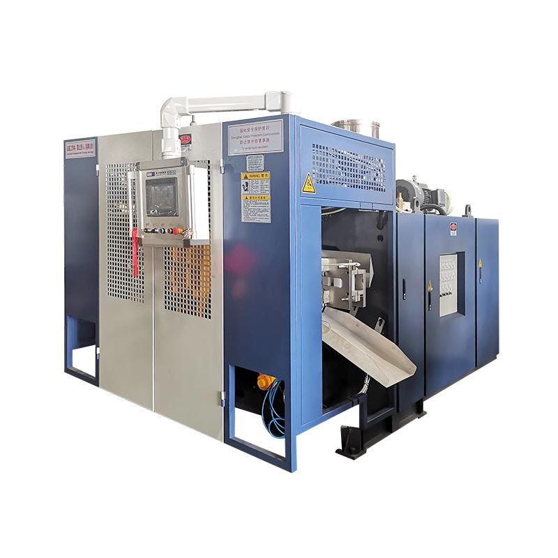
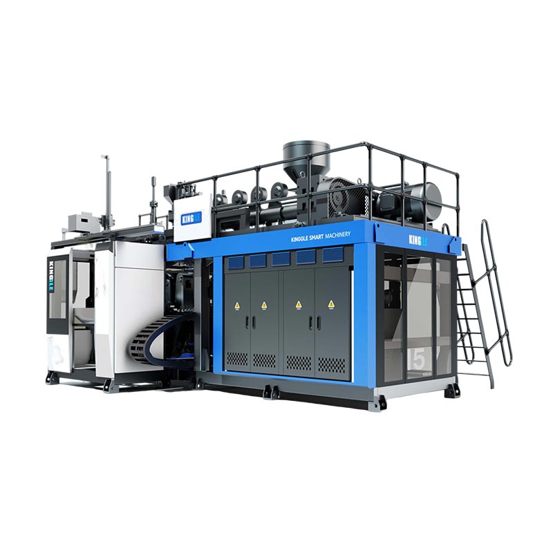
What the Kinggle data reveals about head selection
1. Station count and head geometry are independent choices
Within the 2L pair, both the single- and double-station models publish the same 90 mm single-head limit, 130 mm double-head center distance and 60 mm double-head die-pin limit. The 5L and 15L pairs follow the same pattern within their respective platforms. A second station changes how molds alternate; it does not automatically change outlet count or outlet pitch.
2. A double-head layout has less diameter available per outlet
Every platform publishes a smaller maximum die-pin diameter for the double-head reference than for the single-head reference: 60 versus 90 mm at 2L, 80 versus 150 mm at 5L, and 150 versus 220 mm at 15L. This does not predict finished bottle diameter, but it shows why “add another head” is not merely an output setting. The die, parison and bottle geometry change together.
3. Larger platforms publish wider mold and outlet-spacing references
The maximum mold reference grows from 360 × 380 mm on the 2L pair to 410 × 450 mm on the 5L pair and up to 580 mm wide on the 15L pair. Published double-head center distance grows from 130 mm to 150–180 mm and then 240–280 mm. These figures connect platform selection to bottle spacing, not just nominal liters.
4. Paired double-station models publish more melting capacity
The double-station examples publish higher HDPE melting capacity than their single-station partners: 55 versus 30 kg/h at 2L, 80 versus 55 kg/h at 5L, and 120 versus 100 kg/h at 15L. The differences have no single ratio and do not prove an output multiplier. They show why the extrusion system belongs in the same calculation as stations and heads.
5. Three- and four-head claims need a product-specific drawing
The product descriptions allow flexible 2/3/4 multi-die-head configurations, but their tables do not state a universal triple- or four-head center distance. Inventing those dimensions from the double-head row would ignore bottle width, mold steel, pitch, neck location and service access. The correct next document is a proposed head-and-mold layout based on the buyer's part drawing.
Select head count from the bottle—not from a desired multiplier
A factory quotation becomes more reliable when the buyer gives the supplier a complete product definition. Begin with the widest and heaviest SKU intended for the proposed tooling family. Then check whether smaller products can share the same machine without forcing an impractical compromise.
Bottle width and center distance
Center distance is measured between adjacent outlet centerlines. It has to match the cavity arrangement closely enough for each parison to enter the correct mold position. Bottle body width is only one part of the requirement. The neck finish, handle, flash pocket, pinch-off area and mold wall between cavities also consume space.
Part weight and gross parison mass
Finished bottle weight is not the mass that the extruder must supply for each event. The gross parison includes the material captured for the bottle plus top and bottom flash and any other trimmed material. Multiply the gross mass of one position by all active positions, then compare the total with the extrusion system at the planned event rate.
Cooling and removal
More cavities can create more heat to remove in every mold close. Unequal water paths can make one cavity the slow position. After the mold opens, the cell must separate, trim, test and convey every part without collisions or excessive accumulation. A molding machine can complete its movement while downstream equipment is already the production bottleneck.
SKU strategy
A high-cavity mold can suit a stable, narrow bottle family. It may be less attractive when orders are short, designs change often or a large share of SKUs cannot use the same pitch. Compare annual good-part demand and changeover time by SKU. Do not size every mold around one seasonal peak unless the rest of the factory can use that capacity.
Calculate realistic output with events, parts and mass balance
Catalogue dry cycle and head count are not enough to forecast sellable bottles. Use two connected calculations: one for accepted parts and one for gross melt demand.
Good parts per hour = stable molding events per hour × parts formed per event × accepted fraction
Gross melt demand (kg/h) = stable molding events per hour × total gross parison mass per event (kg)
The accepted fraction must come from the buyer's quality definition and an agreed trial or honest planning assumption. Total gross parison mass is the sum of all parisons used in one event. If four outlets do not deliver identical mass, record the four positions separately before adding them.
A transparent hypothetical example
Assume a proposed four-outlet layout forms four bottles per event. During a stable trial—not a dry cycle—the cell completes 300 molding events per hour. If the agreed accepted fraction is 0.97, calculated good output is 300 × 4 × 0.97 = 1,164 bottles per hour. If total gross parison mass per event is 0.44 kg, gross melt demand is 300 × 0.44 = 132 kg/h.
Those numbers are a teaching example only and are not a Kinggle model result. They demonstrate why a four-head machine is not automatically suitable: the proposed extruder would need verified capacity for the material and conditions, while cooling and all downstream steps would need to sustain the event rate and quality. Substitute measured project data before making a purchase decision.
Kinggle's continuous blow molding machine guide explains how station count, die-head cavities and cycle time combine. For plant planning, also verify electrical, compressed-air and cooling conditions with the blow molding machine utility guide.
Factory commissioning: qualify every outlet and cavity as a position
A combined average can hide a weak position. If three bottles pass a weight check and one is light, their average may look acceptable even though one cavity is unstable. During factory acceptance and startup, label each die outlet and cavity position and preserve that identity through trimming and inspection.
Establish a position-by-position baseline
- Identify the machine, die head, mold, resin lot, recipe and utility conditions.
- Collect parts in sequence from every outlet/cavity position.
- Record gross parison mass where the agreed safe trial method permits it.
- Measure finished weight and the same critical wall locations for each position.
- Inspect pinch-off, neck finish, flash, dimensions, appearance and leak performance.
- Record event interval, rejects, alarms, manual intervention and downstream stops.
- Repeat after stable conditions are restored following any approved adjustment.
Change one controlled factor at a time
If one parison differs, first decide whether the pattern follows the die outlet, cavity, cooling circuit or downstream position. A coordinated record is more useful than adjusting several HMI values at once. Kinggle's HMI settings and alarm guide recommends recording evidence before changing a recipe.
Check wall distribution, not only total weight
Two bottles can weigh the same and still distribute material differently. Compare defined shoulder, body, handle, base and pinch-off locations where relevant to the part. If the project uses programmed wall control, the parison programming guide provides a structured method for connecting program points to measured regions.
Turn the accepted trial into a maintenance reference
Keep the approved position data, temperature conditions, cleaning state, water conditions and tooling identity. When one position later drifts, maintenance can compare it with the original baseline. The preventive maintenance checklist can carry those observations into routine inspections.
Common combinations—and what each description still leaves open
| Short description | What it probably means | What the RFQ must still confirm |
|---|---|---|
| Double-head, two-cavity machine | Two parisons feed two mold cavities per molding event | Station count, outlet pitch, mold size, part weight, extrusion capacity and downstream scope |
| Four-head bottle blowing machine | Four die outlets form four parisons in parallel | Whether the mold has four corresponding cavities, the exact pitch and whether all SKUs fit |
| Double-station, double-head machine | Two mold stations alternate around a two-outlet die system | Number of mold sets, event sequence, melt demand, removal method and guaranteed trial conditions |
| Four-cavity blow molding machine | One mold close can form four parts | Die outlet arrangement, station count, cavity balance, cooling and accepted output |
| Double-layer, double-head machine | A multilayer system may feed two outlets | Extruder count, material structure, layer ratios, scrap route, outlets, cavities and stations |
“Plastic bottle making machine,” “HDPE bottle blowing machine,” “extrusion bottle machine,” “multi-die head blow molder” and “multi-parison extrusion blow molding machine” can all appear in searches for related equipment. A technically complete specification should remain understandable even when those marketing names change.
RFQ checklist for a multi-head blow molding project
Send the same product and factory inputs to each supplier. Ask each quotation to respond in the same order, with catalogue references separated from project guarantees.
| RFQ group | Information to provide | Required supplier response |
|---|---|---|
| Product | 2D/3D drawing or samples, capacity, maximum dimensions, neck, handle, parting line and trim geometry | Compatible machine platform, orientation, cavity layout and any design concerns |
| Material | Exact resin grade, color/additives, regrind or PCR plan and supplier data | Proposed screw/extrusion scope, processing assumptions and trial material requirement |
| Mass and quality | Finished weight, estimated gross parison/flash, critical walls, dimensions and functional tests | Trial method, sampling by position and acceptance definition |
| Output | Required good parts per hour, shift/year volume, SKU mix and changeover frequency | Events per hour, parts per event, assumed accepted fraction and gross melt calculation |
| Tooling | Existing molds or preferred cavity concept | Outlet count, center distance, die-pin range, mold size, cavity pitch, mold sets and cooling design |
| Machine | Preferred automation level and factory constraints | Station count, clamp, extruder, controls, take-out and included options |
| Factory | Power standard, air/water conditions, ambient limits, floor, height and lifting route | Project utility sheet, general arrangement, foundation/loading and service-clearance requirements |
| Downstream | Trimming, leak testing, conveying, labeling, packing and scrap-handling plan | Capacity and interface boundary for each included and buyer-supplied stage |
Do not accept an output line without its test conditions
A useful acceptance document names the bottle drawing, material grade, finished and gross weight, active outlets and cavities, mold cooling conditions, stable run window, quality tests, sampling plan and included downstream equipment. It records accepted parts by position. Without those conditions, “pcs/h” can describe machine movement, formed parts before inspection or good packed bottles—three different results.
Ask for the layout before freezing the purchase order
The final drawing should show die-outlet centerlines against the mold cavities, mold and platen boundaries, blow pins, trimming or deflashing method, take-out path and service clearances. For a triple- or four-head Kinggle request, this drawing is where project-specific pitch is confirmed; it should not be inferred from the published double-head table.
Frequently asked questions
What is a multi-head blow molding machine?
A multi-head blow molding machine uses a die-head arrangement with several outlets to form several parisons at one molding event. The outlet count, center distance and die size must match the bottle and mold-cavity layout.
Is a double-head machine the same as a two-cavity machine?
No. Double head describes two die outlets or parisons; two cavity describes two part shapes in the mold. They are commonly designed as a matched two-part layout, but the quotation should specify both separately.
Does a four-head blow molding machine make four times more bottles?
Not automatically. It can form more parts per molding event, but actual good output depends on stable event rate, total gross melt demand, outlet and cavity balance, cooling, trimming, testing and accepted quality.
How is die-head center distance selected?
Center distance is selected from the proposed cavity pitch and product layout. Bottle width, neck position, flash pockets, mold steel, cooling, blow pins, trimming and removal space all affect the final dimension.
Can one machine switch between single and multi-head production?
A different die-head or tooling arrangement may be possible on a suitably engineered platform, but it should not be assumed. Confirm mechanical fit, extrusion scope, controls, changeover work, mold compatibility and commissioning requirements with the supplier.
What limits the number of cavities in extrusion blow molding?
Limits include product dimensions, available mold and platen space, outlet pitch, die and parison geometry, clamp requirements, extrusion capacity, cooling balance, part removal and downstream capacity.
What data should I send for a multi-cavity machine quotation?
Send the part drawing or samples, material grade, finished and gross parison weight, critical walls and tests, required good output, SKU plan, factory utilities, layout limits and downstream requirements.