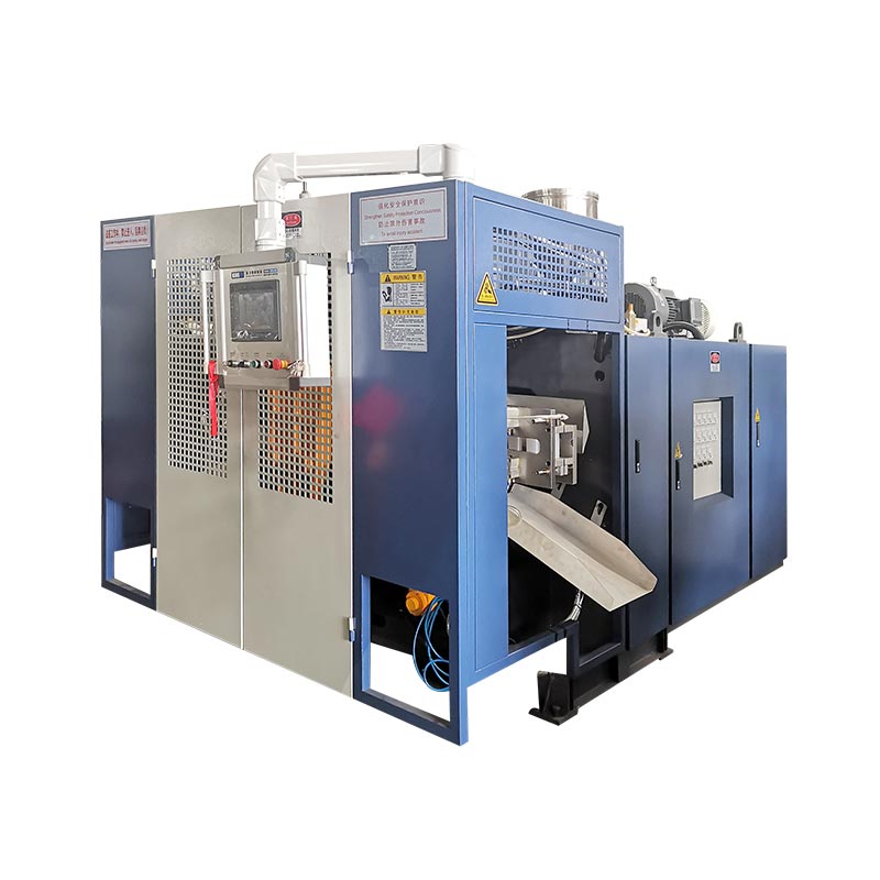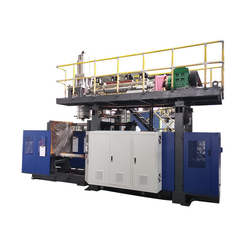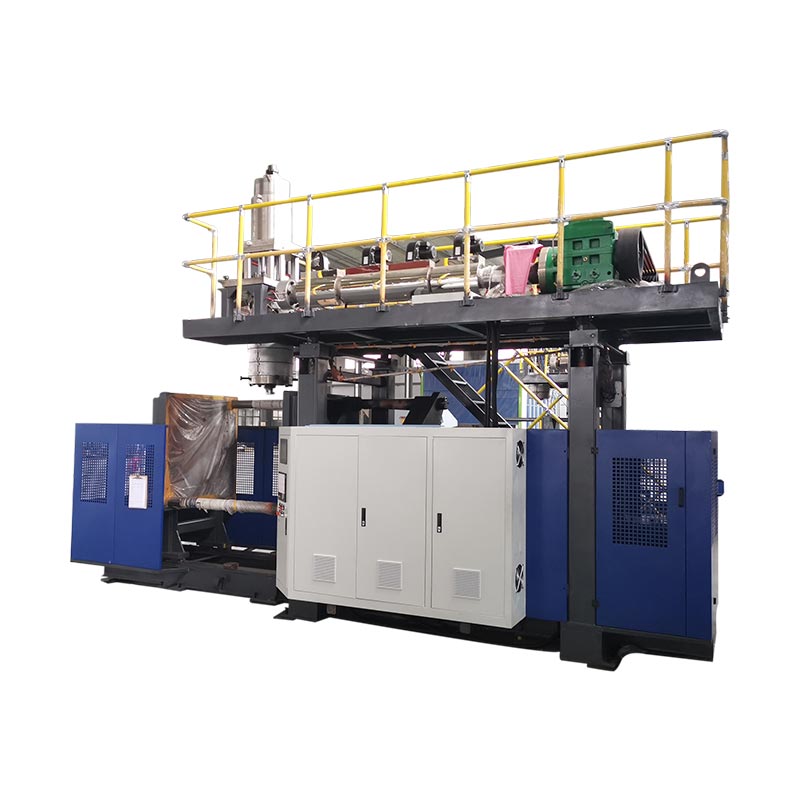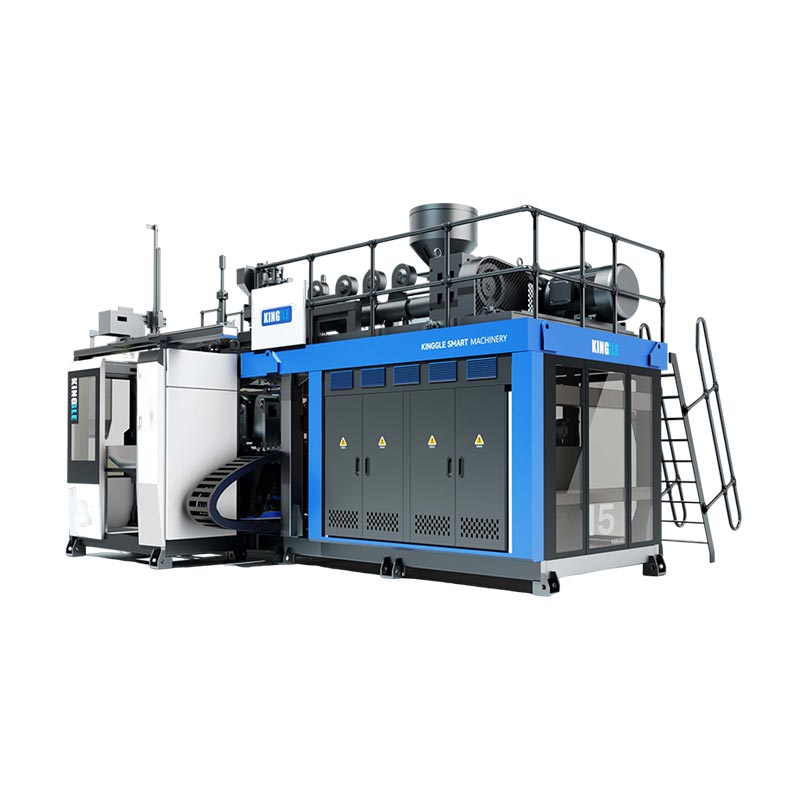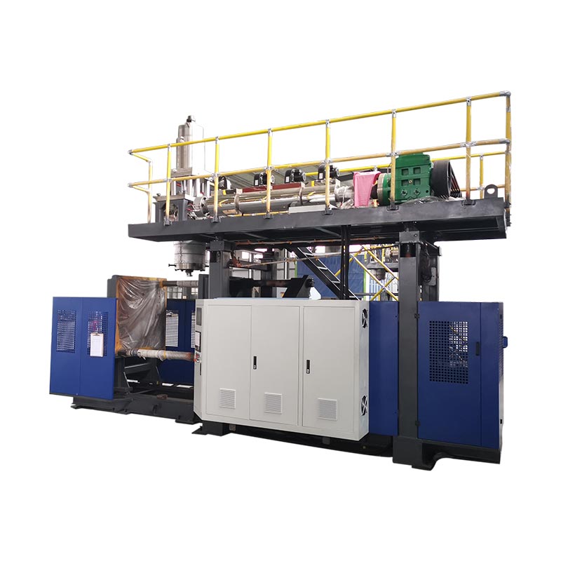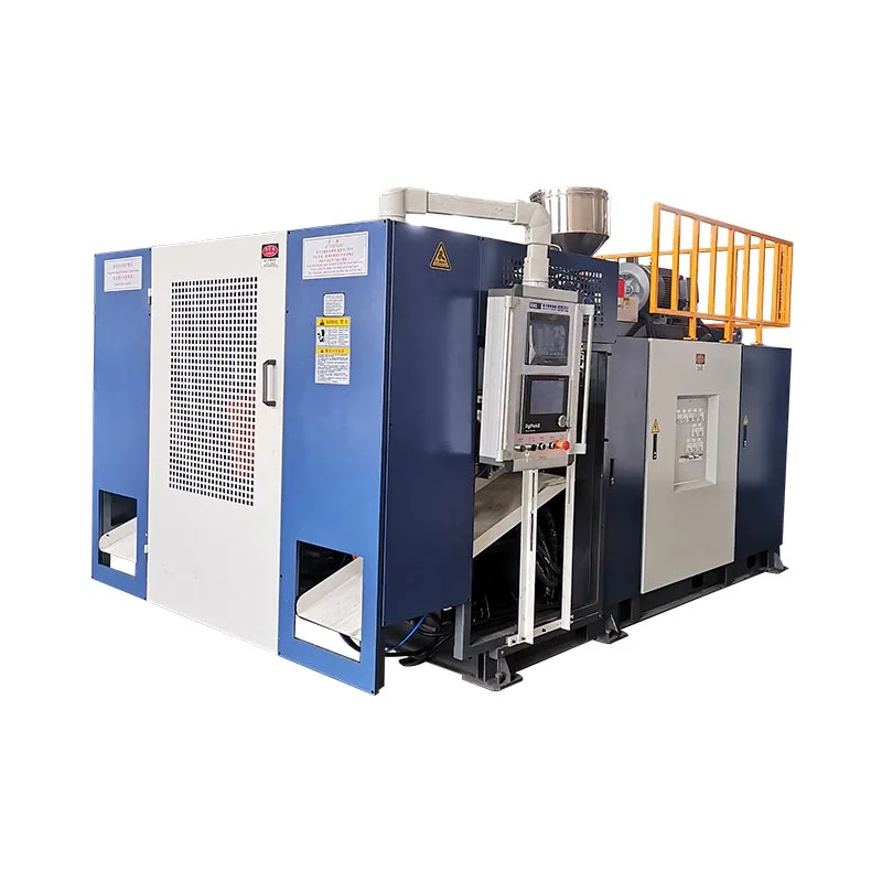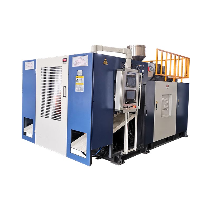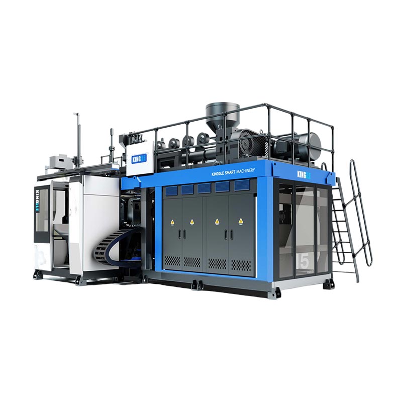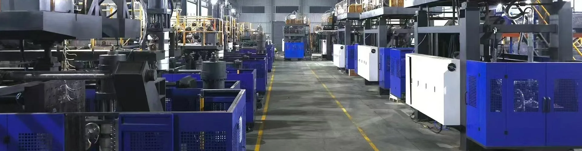
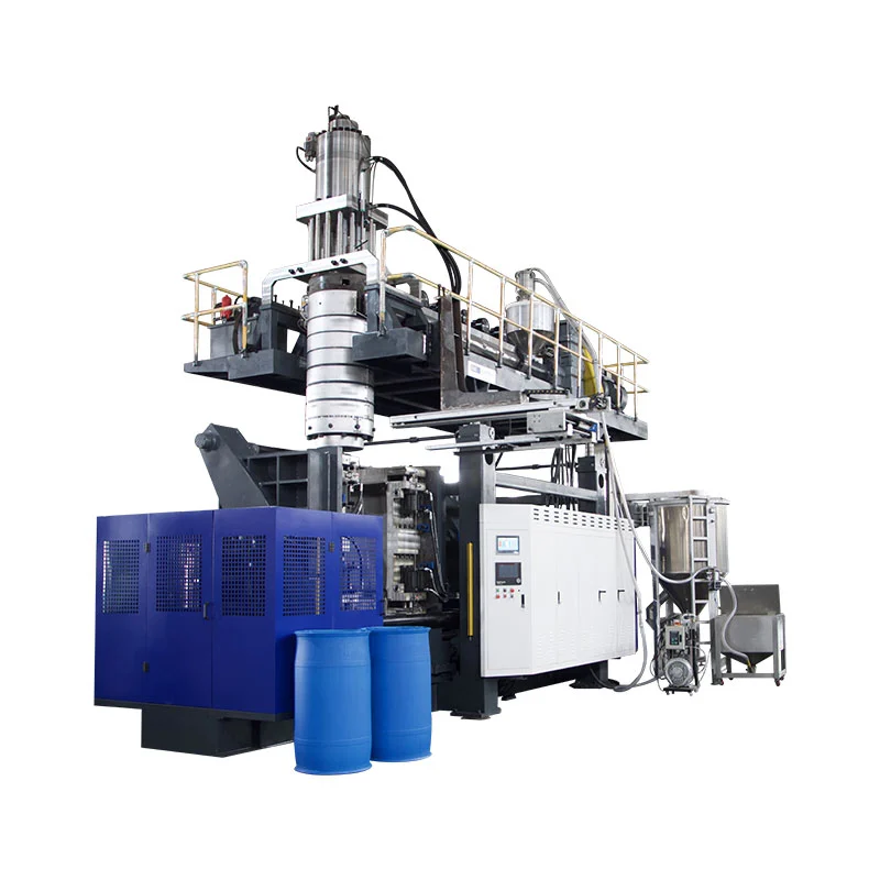
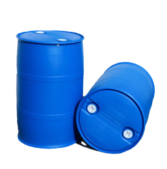
The KGB200L/LP is Kinggle's 250L-class accumulator blow molding platform for 220L double-ring chemical drums. A working project needs more than the molding machine. It also needs an approved drum specification, matched HMWHDPE, mold and cooling design, parison program, take-out and deflashing, leak testing, traceable quality checks and a factory acceptance plan.
A chemical drum line should be planned from the finished package backward. The drum must hold the intended contents. It must survive the defined handling and transport tests. Its closures, wall map and production records must stay under control. A fast dry cycle alone proves none of those things.
This guide follows one drum through the complete cell. It separates published machine data from project inputs. It also shows which results must be proved during a production trial.
- Freeze the drum drawing, closures, material, net weight and wall map.
- Convert finished weight into gross parison mass, including all trim.
- Match the head, parison program, mold and cooling to the critical zones.
- Define handling, deflashing and inspection as part of the cycle.
- Accept the line with approved resin, production settings and measurable pass criteria.
What a complete 220L chemical drum cell actually includes
The machine forms the hollow body. The cell makes repeatable, accepted drums. That distinction changes the purchasing list. It also changes the questions asked during engineering.
Upstream equipment may include resin storage, conveying, drying or blending when the formulation requires it. Color and additive dosing need controlled recipes. Regrind needs a defined source, particle condition and permitted ratio. These items determine what reaches the extruder. An unstable feed cannot produce a stable parison.
The core cell contains the extruder system, accumulator head, clamping unit, mold, blow pins or bottom-blowing arrangement, hydraulic system and controls. Kinggle's KGB200L/LP product page also lists a MOOG 100 thickness controller, robot arm and bottom blowing system in its published description. The final order should identify the exact supplied versions.
Downstream work starts when the mold opens. The hot drum needs controlled removal. Top and bottom flash must be cut without damaging sealing surfaces. Openings may need machining or finishing. Closures may need fitting. Each accepted drum then needs the agreed dimensional, weight, wall and leak checks.
Cooling equipment, compressed air, material handling, trim collection and safe access sit around this cell. A laboratory or quality area may sit outside it. That area handles longer tests, retained samples and record review.
A complete scope also names each boundary. Who supplies the mold chiller? Who provides the compressor and receiver? Who connects the robot guarding? Who supplies the leak tester? If a boundary has no owner, it often becomes a startup delay.
Lock the drum specification before selecting the final configuration
The phrase “220 litre drum” is not a full specification. Two drums can share nominal volume yet need different process conditions. A closed-head double-ring drum has different necks and handling zones from an open-head design. The closure system, contents and transport route also affect testing.
Begin with a controlled drawing. Include overall dimensions, nominal and brimful capacity, openings, closure details, chimes, rings, handles and label areas. Mark the parting line and pinch-off. Identify every dimension that affects filling, palletizing, stacking or cap fit.
Add a numbered wall-thickness map. The map should cover the top ring, shoulder, sidewall, lower ring, base, necks and pinch areas. One average wall number cannot show how resin is distributed. Kinggle's page lists 3.5 to 4 mm for its published 200L application. Use that as a page-specific reference, not as a substitute for the approved wall map.
Record the net molded weight. Do not include separately assembled closures. Then estimate top flash, bottom tail, neck scrap and any other trimmed material. This creates the gross parison target. A 12 kg finished drum may need a shot above 12 kg because the process must also form removable material.
The intended contents belong in the file. Add density, viscosity, filling temperature, vapor pressure, chemical compatibility requirements and expected storage time. The buyer should also state whether the drum will carry regulated dangerous goods. That answer changes the validation path.
Kinggle's sales process asks for photos, drawings, weight, size, material, thickness, daily output and chemical resistance. Those inputs should be one revision-controlled drum dossier. The quotation, mold design and acceptance plan should all point to the same revision.
Read the KGB200L/LP published data as one matched set
The KGB200L/LP page provides a useful starting envelope. It identifies a 250L maximum container class, a 39 t machine and a fixed open-closing arrangement. It also lists a 760 kN clamping force, a 1300 by 1500 mm platen and an 1100 by 1700 mm maximum mold size.
The public extrusion table shows two 100 mm screws with 32 L/D ratios. Published HDPE melting capacity is 180 kg/h per screw. The table also lists a 25 L accumulator and an 18 kg PE accumulator-weight reference. These are machine-page values. They do not prove a particular drum, resin or cycle without a matched trial.
| Published KGB200L/LP item | Website value | What the project still must check |
|---|---|---|
| Maximum container capacity | 250 L | Actual mold, shot demand, geometry and removal path |
| Machine size and weight | 9.5 x 4.1 x 6.5 m; 39 t | Service clearance, foundation, transport split and lifting plan |
| Clamping force | 760 kN | Projected area, blow pressure, pinch-off load and margin |
| Maximum mold size | 1100 x 1700 mm | Complete mold envelope, hoses, manifolds and moving parts |
| Mold thickness | 810 to 950 mm | Closed mold stack and platen interface drawing |
| Screw and L/D | 100 mm x 2; 32 L/D | Ordered layer architecture, resin grade and color system |
| Published HDPE melt capacity | 180 kg/h x 2 | Stable output with the approved HMWHDPE formulation |
| Accumulator | 25 L; 18 kg PE reference | Gross parison mass, reserve and programmed profile |
| Blow air | 0.8 MPa; 1.8 m³/min | Required air quality, peak flow, receiver and pressure at machine |
| Cooling water | 0.3 MPa; 120 L/min | Supply temperature, return temperature, quality and heat load |
| Published power reference | 70 to 80 kW average | Measurement boundary, product, settings and production state |
The page also displays 300 pcs/h as “Output (dry Cycle).” That is not production output for chemical drums. It describes a dry machine movement reference. The same page separately publishes 17 to 20 drums per hour for its chemical-barrel application. Keep both labels intact.
The correct acceptance target is neither number by itself. It is accepted drums per agreed time under approved production conditions. The run must include extrusion, blowing, cooling, take-out, trimming, inspection and counted stops.
Read the data in connected groups. Mold dimensions belong with opening stroke and the removal path. Accumulator mass belongs with gross shot mass and resin. Air flow belongs with pressure at the machine. A single large value cannot compensate for a weak match elsewhere in the cell.
Why the /LP suffix should not disappear from the quotation
Kinggle currently publishes two related product pages. One names the KGB200L/LP specialized chemical-barrel platform. The other names the KGB200L 220 litre plastic drum machine. Their shared 250L class does not make the model names interchangeable.
The KGB200L/LP page lists a 39 t machine and two 100 mm screws. Its description centers on a double-layer accumulator head. The KGB200L page lists a 36 t machine and one 120 mm screw. It publishes 320 kg/h for HDPE. Both pages show the same broad mold envelope and 760 kN clamp reference.
That difference points to architecture, not just capacity. A two-extruder layout can support an ordered layer structure or material split. A single-extruder layout serves a different melt path. The exact function of each layer still needs a written process diagram. Never assume that two extruders automatically create a required barrier, recycled-content structure or color arrangement.
KGB200L/LP public positioning
Specialized 220L double-ring chemical-drum platform. The page lists two 100 mm screws, a double-layer head description and a 39 t machine weight.
KGB200L public positioning
220 litre plastic drum machine. The page lists one 120 mm screw, 320 kg/h HDPE melt capacity and a 36 t machine weight.
A purchase order should include the full model, revision and configuration. Attach a process-flow drawing. List every extruder, motor, screw, head passage and controller. Show which material feeds each passage. If layer ratio is controlled, define its working range and verification method.
This control protects both sides. The buyer receives the intended architecture. The supplier receives a stable technical target. It also keeps spare-parts lists, electrical drawings and operator training aligned with the installed machine.
Control HMWHDPE as a production input, not a generic label
Kinggle's application reference names HMWHDPE. The acronym describes high molecular weight high-density polyethylene. It does not identify one exact grade. Drum performance depends on the selected resin, formulation, processing history and package design.
The approved material file should name the supplier and grade. Add the material data sheet, color masterbatch, additives and change-control rules. Record how incoming lots are identified. If an alternative grade is allowed, state the approval test before it enters normal production.
Regrind needs its own rule. Separate clean in-process trim from post-use recycled material. Define the permitted source, preparation, particle size, storage and blend ratio. Record how operators respond when the grinder or conveyor stops. A percentage on a recipe screen has little value if the actual feed stream is not controlled.
Moisture, contamination and fines can disturb feeding or surface quality. Material temperature and bulk behavior can also change recovery. Inspect the real system during the production trial. The resin should travel through the intended hopper, blender, conveyor and regrind loop.
If the drum will carry chemicals, compatibility belongs to the finished package program. The molding machine cannot establish compatibility by itself. The intended substance, storage duration, environmental exposure and applicable rules determine the evidence.
A material change can shift melt strength and sag. It can alter how the parison stretches around rings and corners. That is why material approval and parison programming should not be managed as separate projects.
Build the parison around rings, shoulders, base and closures
A large drum does not stretch evenly. The shoulder travels over one part of the mold. The lower corner travels over another. The rings, base contact and neck areas each ask the parison for different material. One die gap cannot serve every zone equally.
Start with mass. Add the finished drum, top flash, bottom flash, neck scrap and other trim. This is the gross parison mass. Compare it with the ordered accumulator capacity under the approved resin basis. Leave an engineering reserve instead of matching the published maximum exactly.
finished drum mass + top flash + bottom tail + neck or handle scrap + other trimmed material
Next, map the parison along its length. Use the numbered wall map from the approved drum. Connect each critical drum location to a position in the parison program. The first profile is only a starting recipe. The production trial should update it from measured wall results.
Watch the double-ring zones. Too little material can reduce local wall or change ring geometry. Too much can increase weight, cooling time and flash. The necks and closures need stable geometry. The base needs enough material for contact and impact performance. None of these goals is solved by making the whole drum heavier.
Accumulator discharge also matters. The parison should enter the mold within a controlled time. Melt temperature, discharge speed, die-gap motion and mold close timing interact. If the parison hangs too long, sag changes the wall map before the mold closes.
Store the final profile with a revision number. Record the die tooling, resin, temperature setpoints, discharge time and sample wall map. A profile without those conditions is difficult to reproduce.
Treat the drum mold and cooling circuit as one design decision
The public mold envelope is only a fit check. It does not prove that the mold will cool evenly, release the drum or clear the robot. Review the complete mold assembly. Include manifolds, hose bends, blow hardware, moving inserts, pinch blocks and lifting points.
The parting line and pinch-off must manage a heavy parison. The cut should seal consistently without trapping excessive material. Flash pockets need room for the expected mass. Neck and bottom-blow details must match the drum drawing and downstream finishing method.
Cooling should follow the drum's thermal load. Rings and thick transitions can hold heat. Broad sidewalls can deform during removal. The base and closure zones may need tighter temperature control. Design channels around these needs instead of using one simple circuit for the whole mold.
Split the mold into named cooling zones. Give each zone a target flow and inlet condition. Provide accessible connections and a flushing plan. During the trial, record supply and return temperatures. A pressure reading alone cannot show whether heat is leaving each circuit.
Removal temperature is part of the cycle. An early release may increase output while the drum is still soft. The robot, conveyor or operator can then distort rings or sealing surfaces. Define a safe removal condition with dimensional and functional evidence.
The Kinggle page lists 0.3 MPa and 120 L/min as machine cooling-water references. These values help size the connection. They are not a complete chiller specification. The final cooling package needs water temperature, ambient design condition, mold heat load, machine heat load, flow stability and water quality.
Use the extrusion blow molding mold design guide to review venting, pinch-off, cooling and release. Put the accepted mold drawing in the same technical file as the machine layout.
Plan take-out, deflashing and leak testing inside the cycle
The molding cycle does not end when the mold opens. A large drum still needs safe removal and controlled finishing. These steps can become the real output limit if they are added after the machine is built.
Start with take-out. Define the grip location, drum temperature, payload and movement path. The robot must clear the mold, guarding and blow hardware. Its grip should not crush a warm ring or mark a label panel. The handoff point should support the drum without uncontrolled rolling.
Next, map every cut. Top flash, bottom tail and neck material may need different tools. Protect closure faces and critical dimensions. Collect trim without mixing it with floor debris. If clean trim returns to the process, show the route to the grinder and blender.
Leak testing needs a written boundary. Define the tested openings, closure condition, pressure or vacuum method, stabilization time, test time and reject threshold. Also define what happens after failure. A rejected drum should remain traceable to its cavity, time window and process record.
| Station | Input | Output | Evidence to capture |
|---|---|---|---|
| Robot take-out | Warm molded drum | Supported drum at trim station | Clearance, grip marks, cycle time and repeatability |
| Deflashing | Drum with process trim | Clean finished edges | Cut quality, drum damage and trim mass |
| Opening finish | As-molded necks | Closure-ready interfaces | Dimensions, surface and gauge results |
| Leak test | Finished drum and test closures | Pass or traceable reject | Recipe, result, instrument ID and timestamp |
| Final inspection | Tested drum | Accepted product or controlled reject | Weight, wall map, dimensions and appearance |
Time every station during the factory trial. A molding machine may wait because the take-out route is long or the trim station is full. Those delays belong in accepted output. They should not be hidden behind the dry-cycle number.
Separate machine capability from UN packaging approval
Kinggle's product page states that drums from the published application can pass a 3 m drop test and complete UN certification. Keep that claim tied to the stated application. Do not rewrite it as a guarantee for every drum, filling substance or market.
A machine cannot grant a UN packaging mark. Approval applies to a packaging design type under the relevant system. The finished drum, closures, contents or test media, preparation, conditioning and test results all matter. Ongoing manufacturing controls also matter after the design passes.
The United Nations Economic Commission for Europe publishes the UN Model Regulations. Revision 24 was published in 2025. The applicable national or modal rules may use a particular edition or add requirements. Confirm the authority, test laboratory and approval route for the destination market.
Build two evidence layers. The first is the machine factory acceptance test. It proves that the ordered cell runs the agreed drum under defined conditions. The second is packaging design-type testing. It proves the finished packaging against the applicable program. One does not replace the other.
During machine trials, measure the features that support later testing. Record net mass, gross shot mass, wall map, closure dimensions, ring geometry, leak result and process settings. Retain labeled samples. This gives the packaging test team a traceable starting lot.
For more detail on product testing intent, use Kinggle's existing chemical drum drop-test guide. Keep the present article focused on the production cell. That separation helps buyers find either the machine-integration answer or the testing answer without reading two pages that say the same thing.
Calculate accepted output from real production events
The product page publishes 17 to 20 drums per hour for its named application. That is a useful planning reference. It is not a guaranteed rate for a different drum. Weight, wall map, resin, mold cooling, take-out and inspection can all change the result.
Start with a timed run. Count every molding event. Then classify each drum as accepted, rejected or awaiting a test. Record every stop and its cause. Use the same quality plan that will govern production.
accepted drums ÷ observed production minutes x 60
Also calculate gross material demand. Multiply gross parison mass by molding events per hour. Do not multiply the finished drum weight by a catalog rate. That shortcut ignores flash, rejects, start-up material and other process losses.
gross parison mass x molding events per hour
Separate first-pass yield from rework or retest. A drum that fails the leak station and later passes after closure adjustment should not disappear from the event log. The reason matters. It may point to molding, finishing, closure assembly or the tester.
Cooling often controls the cycle. If an extra few seconds protects ring geometry, that time belongs in the accepted rate. A faster release that creates oval necks or unstable dimensions is not a productivity gain.
Use a long enough run to expose recovery and downstream balance. Record machine settings at the start and end. The cycle-time guide explains how to separate extrusion recovery, molding, cooling and handling. The energy guide explains why power and energy per accepted drum need a stated measurement boundary.
A useful final KPI set includes accepted drums per hour, first-pass yield, gross kilograms per accepted drum, trim kilograms per drum, counted downtime and energy per accepted drum. Each number needs an agreed start and stop rule.
Plan the factory boundary around peaks, access and heat removal
The public machine dimensions are 9.5 by 4.1 by 6.5 m. That box is not the installation space. Operators, mold changes, platforms, cabinets, pipes, conveyors and guarding extend beyond it. The roof must also allow erection and maintenance.
Begin with the equipment layout drawing. Add maintenance pull space for screws and hydraulic components. Mark the mold path from truck or storage area to the platens. Check the crane or forklift capacity at every point. Show where removed hot drums and flash will travel.
Compressed air needs pressure and flow at the machine connection. Kinggle publishes 0.8 MPa and 1.8 m³/min. The compressor room must account for line loss, other users, peak demand, receiver volume and air treatment. The blowing process also needs the agreed air quality.
Cooling needs stable temperature and flow. The public page lists 0.3 MPa and 120 L/min. Ask for a heat-load sheet that separates the mold, hydraulics and other consumers. Size the chiller or cooling tower for the local ambient condition and water quality.
Electrical planning needs the connected load, voltage, frequency, cable route, protection and transformer check. The page's 70 to 80 kW “average energy consumption” row is a power reference. It is not the installed load and not energy per drum.
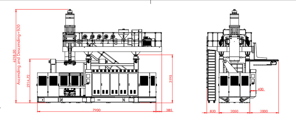
Review the complete blow molding utility plan with the machine and auxiliary suppliers. Put every supply condition and boundary in the technical agreement.
Run an acceptance trial that follows one traceable drum lot
The factory acceptance test should use the approved drum drawing, mold and material. If production resin is unavailable, document the substitute and the limits of the result. Do not call a dry machine movement a product acceptance test.
Agree the test plan before the visit. Name the instruments, sample size, run duration and acceptance limits. Decide how stops are counted. Define which settings may change during the run and who approves a change.
- Verify the build. Check the full KGB200L/LP model, extruders, head, controller, clamp, robot, bottom blowing, guarding and ordered auxiliaries against the contract.
- Verify calibration and utilities. Record instrument IDs. Confirm power, air and cooling conditions at the machine boundary.
- Load the approved material. Record resin grade, lot, color, additive and regrind recipe. Follow the intended conveying path.
- Stabilize the process. Reach repeatable melt conditions, accumulator recovery, discharge behavior, cooling and take-out before starting the formal run.
- Freeze the starting recipe. Save temperatures, speeds, parison profile, timings, pressures and downstream settings with one revision number.
- Run the agreed window. Count molded, accepted and rejected drums. Log each stop with duration and cause.
- Measure the sample plan. Check mass, dimensions, wall map, ring and neck geometry, trim quality, appearance and leak result.
- Audit the downstream balance. Confirm the robot, trimming, tester and conveyors can sustain the molding rate without unsafe accumulation.
- Close every deviation. Record the result, owner and retest method. Do not hide an open issue in a general “test passed” statement.
Retain samples from the start, middle and end. Label each drum with time, recipe and result. Keep the wall map and leak record with the trial report. This turns a factory visit into evidence that can support later startup and troubleshooting.
Photograph the approved samples and their labels. Export the final recipe before shutdown. The report should also list unresolved observations that did not trigger rejection. These details give the site team a clear restart point after installation.
Functional package tests can be witnessed during the machine project if the method is agreed. Yet formal design-type approval may happen elsewhere. Keep those reports separate. Each report should state exactly what it proves.
Kinggle's sales process includes inspection, testing and an invitation to join the test. Use that opportunity to follow the factory acceptance test guide. After delivery, repeat a defined site acceptance run with the installed utilities and local material system.
Build a quotation-ready RFQ for the KGB200L/LP cell
A useful inquiry lets the supplier check the whole production path. Start with the drum file. Add a drawing, photos and a physical sample if available. State whether the product is 200L, 220L or another size within the proposed class.
Provide net molded weight, gross shot estimate and the numbered wall map. Name the HMWHDPE grade, color, additives and regrind rule. State the contents, closure system, chemical-resistance requirement and applicable package tests.
Define output as accepted drums per hour. Add annual volume, shift pattern and planned changeovers. Describe take-out, trimming, opening finish, leak test, inspection, marking and palletizing. Mark which items Kinggle should quote and which the buyer will supply.
Attach the factory data. Include voltage, frequency, compressed-air capacity, cooling source, ambient range, altitude, building height, crane capacity and available floor plan. Add the preferred machine orientation and drum flow.
Ask for a written response with the full KGB200L/LP configuration. It should include mold envelope, extruder and head architecture, accumulator basis, utilities, auxiliary list, layout, acceptance plan and data handover. Do not accept “standard configuration” as the only description.
The final decision should connect every important drum requirement to a machine feature or test. If one requirement has no owner, close it before order release. If you are still collecting files, use Kinggle's download center and machine videos for available references. Then send the controlled project package through the contact form.
Frequently asked questions
These answers cover the buying questions that most often change the configuration or acceptance plan. They use the current Kinggle product pages as the machine reference. Project documents should control the final order.
What products is the KGB200L/LP designed to make?
Kinggle positions the KGB200L/LP as a 250L-class specialized machine for 220L double-ring blue chemical drums. A different drum still needs checks for gross parison mass, mold fit, wall distribution, closures, cooling, take-out and required package tests.
Does 300 pcs/h mean the machine produces 300 chemical drums per hour?
No. The product table labels 300 pcs/h as dry cycle. The same page publishes 17 to 20 pieces per hour for its named chemical-drum application. Final accepted output must be proved with the production mold, resin, cooling, automation and quality plan.
Can the KGB200L/LP make a 15 kg finished drum?
The page lists a 12 to 15 kg finished-drum reference and an 18 kg PE accumulator-weight reference. Gross parison mass also includes flash and other trim. Confirm the complete mass balance, resin basis, reserve and wall map before freezing the head configuration.
Is KGB200L/LP the same machine as KGB200L?
No. Kinggle publishes them as related but distinct configurations. The KGB200L/LP page lists two 100 mm screws, a double-layer description and 39 t machine weight. The KGB200L page lists one 120 mm screw and 36 t machine weight.
Does buying this machine give the drums UN certification?
No. A machine does not grant a UN packaging mark. Approval applies to the tested packaging design type under the relevant rules. The finished drum, closures, intended contents or test media, preparation, test results and ongoing production controls all matter.
What should I send for a KGB200L/LP quotation?
Send the drum drawing, photos, sample, dimensions, openings, net weight, wall map, HMWHDPE grade, trim estimate, closures, contents, tests, accepted output target, downstream scope and factory utilities. Also state the required layer structure and automation boundary.
Turn one approved drum into a complete machine specification
Send Kinggle the drum drawing, material, wall map, closures, test plan, output target and factory utilities. The engineering team can then confirm the KGB200L/LP configuration, mold, auxiliaries and acceptance scope.
Request a KGB200L/LP solution