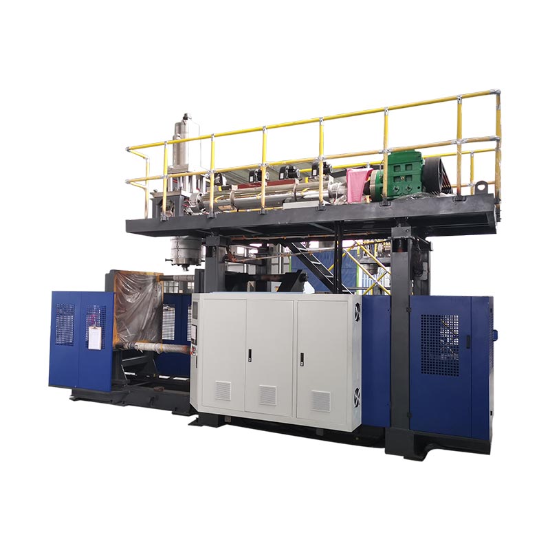
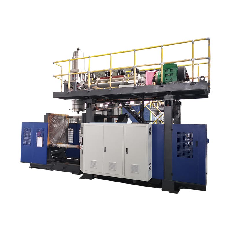
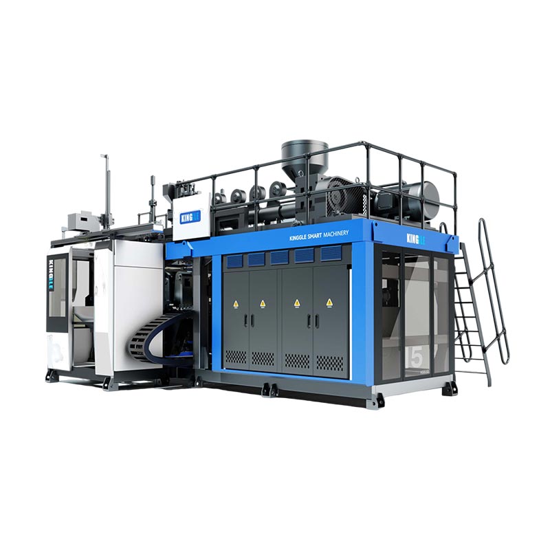
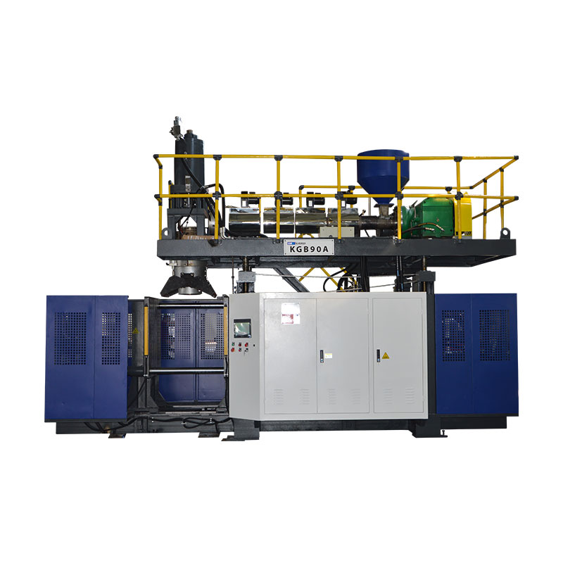
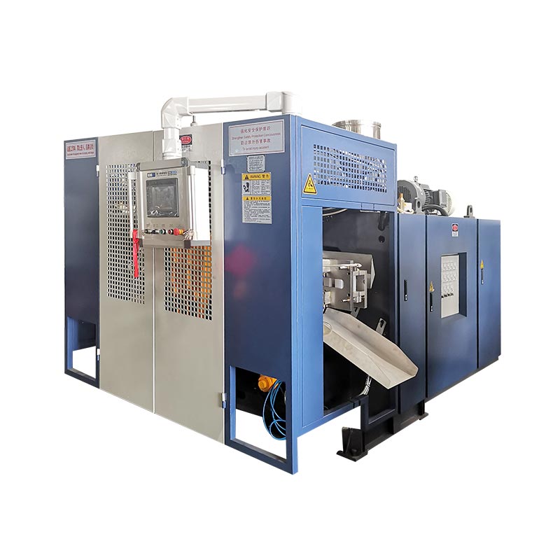
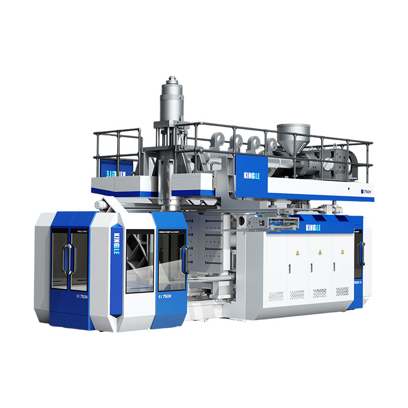
A blow mold is not just the negative shape of a bottle. It has to capture and seal a hot parison, release trapped air, remove heat, create the neck and base, shed flash, fit the clamp and release the part—at the required production rhythm.
Search language can obscure this scope. Buyers use blow mold, blow mould, bottle mold, plastic bottle mould, EBM tooling and extrusion blow mold for related tools. The die head is different: it forms the parison before the mold closes. A quotation should list the die-head tooling and the blow mold as separate items.
This guide focuses on extrusion blow molding rather than injection or stretch-blow preform tooling. It also separates published machine-envelope data from project guarantees. No universal pinch-off, vent or cooling dimension is suitable for every resin and part.
A production blow mold has seven connected jobs
The cavity gives the part its external shape, but shape reproduction is only the first job. The tool must perform the following functions together:
- Locate the parison. The open mold must receive the hot tube without dragging, folding or missing a pinch region.
- Seal and weld it. Pinch-off regions close the parison and manage displaced material at the neck, tail, handle or other flash areas.
- Let trapped air escape. Vents provide a route for air between the expanding parison and cavity surface.
- Transfer heat. Cooling circuits remove heat with enough balance to release a stable part at a repeatable time.
- Create interfaces. Neck inserts, calibration details, blow-pin or bottom-blow features must match the container closure and machine.
- Release and finish the part. Draft, inserts, opening movement and deflashing strategy determine whether the part can leave the mold cleanly.
- Fit and survive the machine. The complete assembly has to fit the platen, opening, thickness and mounting arrangement while carrying repeated clamping and thermal cycles.
A change made for one job can affect another. A deeper flash pocket may change heat concentration around the weld. A polished cavity may reproduce appearance differently while also changing how trapped air travels. A large moving insert may solve an undercut but consume cooling and opening space. Review decisions at system level.
Blow mold anatomy: terms to put on the drawing
The following conceptual view identifies the interfaces a buyer should expect to discuss. It is not a tooling print and contains no manufacturing dimensions.
Cavity surface forms one side of the part. Inserts may define the neck, handle or wear areas.
Located at the closing boundary where the parison is sealed.
Opposing cavity meets at the parting plane. Alignment and mounting control repeatable closure.
Venting routes lead trapped air away from selected cavity regions.
| Feature | Function | Evidence to approve |
|---|---|---|
| Cavity surface | Defines external geometry, texture, markings and local contact cooling | Final part model, shrinkage basis, surface callout and critical dimensions |
| Parting line | Boundary where the mold halves meet | Visible seam location, draft, flash access and effect on functional surfaces |
| Pinch-off / compression land | Compresses and seals parison material while controlling the weld and break line | Material-specific tooling detail and agreed weld/trim test |
| Flash pocket or relief | Receives material displaced beyond the pinch area | Gross parison estimate, flash geometry and deflashing route |
| Vents | Release air trapped outside the expanding parison | Location map, permitted witness marks and cleanability |
| Cooling circuits | Remove heat and control temperature distribution | Channel drawing, circuit identification, flow direction and utility interface |
| Neck and blow interface | Forms or calibrates the finish and introduces blowing air | Closure drawing, blow-pin/bottom-blow concept and trim allowance |
| Mounting and alignment | Connect the mold to the platen and preserve repeatable closure | Machine interface drawing, mass, center of gravity, fasteners and lifting points |
Start with the part and its tests—not a generic cavity
The mold maker needs more than nominal liters. A 5L handled jerry can, a 5L round bottle and a double-wall technical part can require different parting lines, parison diameters, flash layouts and removal sequences.
Map where the parison must stretch
The parison does not fill the cavity like injection-molded melt flowing under high pressure. It expands and stretches toward the cavity wall. Deep draws, broad flat areas, sharp corners, offset necks and handle roots can demand more local material or a different parting-line strategy. Use radii and geometry that can be formed without asking a thin region to stretch farther than the material and process can support.
Put quality locations on the drawing
“Uniform wall” is not a measurable acceptance rule. Mark critical locations and state the test method. The shoulder, corner, handle root, base, pinch weld and panel may have different functional needs. Connect those locations to the parison-programming setup so mold geometry and material distribution are not adjusted independently.
Plan for shrinkage without borrowing an unrelated percentage
Shrinkage depends on resin grade, wall distribution, cavity temperature, cooling time and part geometry. Use material-supplier data as a starting reference, then apply the mold maker's method and validate the actual part. A generic percentage copied from another bottle is not an acceptable cavity-sizing basis.
Parting line, pinch-off and flash must be designed together
The parting line determines where the two tool halves close and where a visible seam can appear. Place it where the mold can open, the parison can be captured, the part can release and trimming equipment can reach the flash. Avoid placing an uncontrolled seam across a sealing surface, important decoration or other functional interface.
The pinch-off is a weld-forming feature
At the tail or base, the opposing pinch regions squeeze two hot parison walls together. The detail has to move enough material to form the weld while creating a controllable break line for flash removal. The correct land, angles, stand-off and pocket depend on the resin, parison thickness, closing action and part. Treat them as engineered dimensions, not a standard block copied across materials.
Published patent literature on extrusion blow molding also treats the pinch region, flash pocket, mold temperature, closing speed and deflashing timing as interacting variables rather than a single edge dimension. This supports a conservative purchasing rule: approve the pinch detail with its resin and trial method, not by appearance alone.
Design the flash route before ordering automation
Identify top flash, tail flash, handle flash and any calibration waste. Decide whether removal occurs in the mold, at a punching station, with a trimmer or through a secondary fixture. Flash mass belongs in gross melt demand, grinder capacity and regrind planning. The tool drawing should also show how removed scrap clears the mold and take-out path.
Cooling and venting decide whether the cavity can work at production speed
Cooling controls when the part is stable enough to leave the mold; venting controls whether the expanding parison can reach the cavity surface. Both are distributed problems. One slow, hot or air-trapped region can set the cycle and appearance for the entire part.
Divide cooling circuits by heat load and control need
Heavy corners, pinch regions, neck inserts and deep features may not release heat at the same rate as a thin straight wall. Several identifiable circuits make it possible to diagnose and balance those regions. Document the inlet, outlet and direction of every circuit. Do not connect a mold to plant water based only on hose diameter; verify required flow, pressure, temperature, water quality and pressure drop for the final tool.
A published finite-element study of extrusion blow molded cooling examined mold material, internal heat transfer, part thickness and initial parison temperature as variables affecting the temperature field and mold-opening time. That research does not provide a cycle-time promise for a Kinggle project, but it reinforces why a mold quotation must define both thermal design and process assumptions.
Locate vents where air can become trapped
As the parison expands, air remains between its outside surface and the cavity. Without a route out, that air can delay contact and contribute to incomplete texture, drag lines or poorly formed detail. The Custom-Pak extrusion blow molding design guide describes parting-line venting and cavity vents near inserts or deep features. The exact vent size and witness-mark allowance still depend on the part and material.
Cleanability is part of the vent design
Vents can lose effectiveness when residue, dust or degraded material accumulates. The mold drawing and maintenance file should show where vents are located, how they connect to atmosphere and how they are inspected without damaging the cavity. Track surface or fill changes by position before increasing blow pressure to compensate for a blocked path.
High-gloss work is a separate thermal project
Colder tooling can favor heat removal, while surface replication can demand a different cavity-temperature strategy. A 2023 peer-reviewed study demonstrated variable-temperature extrusion blow molding on one ABS automotive-spoiler case using controlled heating and water cooling. That is evidence for a specialized approach, not proof that every bottle should use variotherm tooling. State appearance requirements early so the mold and cycle can be designed together.
Neck finish, blowing method and deflashing are one interface
The closure system sets functional dimensions at the top of a bottle. Provide the cap or closure drawing, sealing surface, thread or snap detail, tamper feature and permitted trim condition. Decide whether the finish is formed, calibrated, reamed or cut in a later operation. Do not quote “standard neck” without a controlled drawing revision.
Match the tool to the blowing arrangement
Top blowing, bottom blowing and needle arrangements place air and hardware differently. The blow pin may also participate in neck calibration or flash handling. Confirm stroke, centering, cooling, sealing and collision clearances with the selected Kinggle machine rather than leaving the mold maker to infer them from the bottle alone.
Check downstream gauges against the same datum
A neck can look clean but still fail cap application or sealing. Agree which datums and gauges are used at mold trial, leak testing and filling-line qualification. Preserve gauge identity and calibration status in the acceptance record. If an automated trimmer changes the neck after molding, inspect the finished condition rather than only the as-molded sample.
Original comparison: Kinggle machine references for mold-fit screening
The table below extracts mold-related fields from five current Kinggle product pages. It spans continuous and accumulator machines so buyers can see why nominal container capacity cannot replace a tooling-interface drawing.
| Published model | Machine class | Max container reference | Mold platen size (W×H) | Published max mold size (W×H) | Mold thickness range | Clamping force |
|---|---|---|---|---|---|---|
| KGB2L | Continuous, single station | 2 L | 380 × 430 mm | 360 × 380 mm | 160–300 mm | 40 kN |
| KGB5L | Continuous, single station | 5 L | 368 × 450 mm | 410 × 450 mm | 200–310 mm | 65 kN |
| KGB15L | Continuous, single station | 15 L | 500 × 550 mm | 580 × 500 mm | 300–380 mm | 165 kN |
| KGB80A | Accumulator, fixed mold | 30 L | 750 × 860 mm | 520 × 860 mm | 360–420 mm | 215 kN |
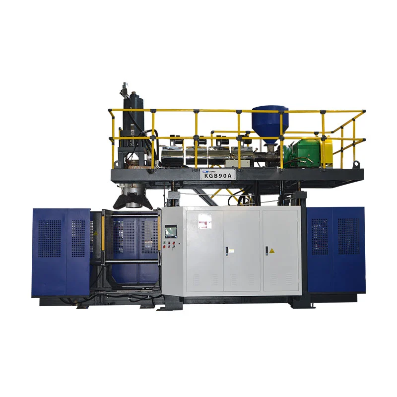
| KGB90A | Accumulator, fixed mold | 60 L | 960 × 980 mm | 700 × 980 mm | 460–550 mm | 280 kN |
Three findings that matter before mold release
First, liters do not define mold orientation. The 15L continuous reference publishes a wider but shorter maximum mold row than the 30L accumulator reference. Architecture and part shape matter alongside volume.
Second, mold thickness has its own range. A cavity can fit the listed face dimensions and still fall outside the permitted thickness or opening arrangement. Backplates, inserts and cooling connections add to the assembly.
Third, clamping force belongs to the product and process. A machine-page value is available force, not evidence that any mold inside the envelope is suitable. Projected area, blowing conditions, pinch-off demand and mold construction require engineering review.
Mold material, inserts and surface finish should follow production duty
Tooling material affects heat transfer, machinability, repair, wear and cost. Production volume alone is not enough to choose it. Consider resin, surface specification, pinch-off duty, abrasive or corrosive conditions, moving features, maintenance capability and the accepted repair strategy.
Base mold material
Ask for the exact alloy or grade, heat treatment where applicable, cavity-manufacturing method and thermal-design basis. “Aluminum mold” or “steel mold” is too broad for comparison.
Replaceable inserts
Neck, pinch-off, wear, thread or vent inserts can localize maintenance and allow a different material at a demanding feature. Record insert identification and spare scope.
Texture and engraving
Specify artwork files, orientation, depth/appearance acceptance, vent interaction and revision control. Confirm how the process will reproduce the requested surface.
Protection and storage
Define cleaning, approved corrosion protection, water draining, transport locks, lifting points and storage conditions. Preserve waterways and pinch surfaces during downtime.
The tooling-maker's material recommendation should state its assumptions and exclusions. When comparing two quotations, check whether both include the same insert materials, cooling scope, engraving, surface finish, hoses, fittings, lifting hardware, trial work and spare wear parts.
Factory trial: prove the mold as a repeatable process
A first acceptable bottle proves that the system can form the part once. Production acceptance requires a stable run with traceable conditions. The following workflow is a recommended evidence structure, not a claim that every Kinggle project already uses the same protocol.
- Confirm identity. Record machine, mold, inserts, die tooling, material grade/lot, color or regrind condition and recipe revision.
- Stabilize conditions. Record actual temperatures, cooling-water supply/return, blow conditions and cycle stages after the process reaches the agreed state.
- Inspect the tool. Check parting-line closure, alignment, water and air leaks, vent condition, pinch-off surfaces and safe movement.
- Sample by position. Keep cavity, outlet and station identity through weighing, wall measurement, trimming and functional testing.
- Measure the finished condition. Include the effects of reaming, punching, deflashing or other included finishing steps.
- Record all losses. Log rejects, stops, alarms, manual corrections and downstream interruptions during the agreed window.
- Save the baseline. Approve the drawing revision, recipe, photographs, measurements, gauges and open corrective actions together.
Diagnose patterns before changing the recipe
| Observed pattern | Tool or process areas to inspect | Evidence to collect |
|---|---|---|
| Weak or inconsistent tail weld | Parison position, pinch detail, mold closure, local temperature, flash relief and deflashing | Position-labeled weld samples, gross mass, close sequence and functional test |
| Poor texture or incomplete detail | Vents, trapped-air location, cavity condition, parison contact and temperature | Defect map, vent inspection, actual process conditions and cavity photos |
| Warpage after ejection | Wall distribution, cooling balance, ejection timing, handling and post-cooling | Temperature/flow by circuit, timed dimensional checks and wall map |
| Flash on one side | Alignment, platen parallelism, parting surface, mold mounting and parison centering | Position history, closure inspection and repeat parts before/after correction |
| Slow or variable cycle | Cooling circuit restriction, hot regions, part thickness, venting and downstream delay | Cycle-stage times, supply/return conditions and stop log |
Use Kinggle's HMI evidence workflow when alarms or sequence changes accompany a mold problem. Carry approved inspection points into the preventive maintenance plan instead of waiting for part quality to drift.
Blow mold RFQ and design-review checklist
- Controlled 2D/3D part file, revision, capacity, maximum dimensions and intended contents.
- Closure and neck-finish drawing, cap samples, sealing datum and finished trim condition.
- Exact resin grade, color/additives, regrind/PCR plan and material-supplier information.
- Finished weight, estimated gross parison and flash route.
- Critical wall and dimensional locations with test methods and acceptance limits.
- Leak, drop, top-load, torque, environmental or other project-specific functional tests.
- Machine model, station and cavity count, die-head outlet plan and parison center distance.
- Platen/mounting interface, mold envelope, thickness, opening, clamp and blow-pin arrangement.
- Parting line, pinch-off, flash pocket, neck insert, vents, cooling circuits and surface finish.
- Take-out, trimming, leak testing, conveying and scrap-handling interfaces.
- Tool material, insert grades, hardness/treatment where relevant, spares and repair method.
- Trial material quantity, run duration, samples, gauges, data record and acceptance responsibility.
- General arrangement, lifting points, mold mass/center of gravity and approved changeover procedure.
- Scope boundary: mold, die tooling, fittings, hoses, drawings, training, packaging and buyer-supplied items.
For factory services, connect the final mold circuits and blowing arrangement to Kinggle's utility and layout planning guide. For machine class and production sequence, use the continuous extrusion blow molding guide and confirm whether an accumulator platform is required for the final part.
Frequently asked questions
What is the difference between a blow mold and a blow molding die head?
The die head forms the molten parison before molding. The blow mold closes around that parison, seals it, receives blowing air, cools the part and defines its external shape. They are separate but connected tooling systems.
What information is needed to design an extrusion blow mold?
Provide the controlled part and closure drawings, resin grade, finished and gross parison weights, critical walls and dimensions, functional tests, output target, machine interface, cavity plan, trimming method and factory utilities.
Why is pinch-off design important in extrusion blow molding?
The pinch-off compresses and seals hot parison material and helps define where flash separates. Its geometry interacts with material, parison thickness, mold closing, temperature, flash relief and deflashing, so it must be validated on the actual project.
Why does an extrusion blow mold need vents?
Air can become trapped between the expanding parison and cavity. Vents give it an escape route so the parison can contact the mold surface and reproduce the intended shape and detail.
How do cooling channels affect blow molding cycle time?
Cooling circuits remove heat until the part can be released without unacceptable deformation. The slowest hot region can limit the cycle, so circuit layout, flow, temperature, mold material and wall distribution must be evaluated together.
Can an existing blow mold fit a different machine?
Possibly, but do not assume it. Check mold width, height, thickness, mass, mounting, opening, clamp, blow-pin position, utilities, take-out path, die-head alignment and controls against the receiving machine.
Should I choose an aluminum or steel blow mold?
The choice depends on thermal performance, production duty, resin, surface and wear requirements, insert strategy, repair capability, lead time and cost. Ask for the exact grade and design assumptions rather than selecting from the metal name alone.