A blow pin delivers air into the parison and, in some extrusion blow molding designs, helps calibrate or finish the container neck. Diagnose neck defects by locating the failure, checking the complete tooling and closure system, then verifying the correction against the product requirements.
Before changing the blow pin
- Identify where the neck first becomes damaged or out of specification.
- Keep samples traceable to the station, cavity and tooling revision.
- Separate alignment and wear from air-delivery, timing and cooling questions.
- Confirm the result with the specified bottle, closure and test conditions.
What does a blow pin do in extrusion blow molding?
The blow pin belongs to the blowing arrangement. It supplies the air that expands a captured parison against the mold. On systems designed for a calibrated finish, the blow-pin assembly also works with the neck tooling. A cutting ring, cooling passage or other finishing feature depends on the actual design; the name alone does not identify the supplied functions.
Eastman describes blow-pin methods for thread-finish calibration and trimming in its extrusion blow molding guide for copolyesters. That is a useful example of the tooling relationship. Its resin-specific setup values should remain with the materials and equipment arrangements described in that guide.
Identify the feature before assigning the cause
A bottle finish includes features with different jobs. The neck bore, external thread and sealing contact area need their own drawing references. The closure may seal against a liner or another designed contact surface. Record the actual sealing arrangement before describing a mark as the cause of a leak.
The external finish comes from the complete tooling and forming sequence. Assigning all of it to the blow pin skips the mating tools. A dimensional complaint should therefore identify the feature, the measurement method and the tools that influence it.
A die pin and an IBM core rod are different references
The die pin or mandrel belongs to the melt-forming tooling at the die head. Confusing that component with the blow pin can lead a maintenance request toward the wrong assembly. Use the part drawing and assembly identification rather than a workshop nickname.
Injection blow molding uses a different preform-and-core arrangement. This guide addresses extrusion blow molding neck checks. For mold features beyond the neck, the extrusion blow mold design guide explains the wider relationship between forming, cooling and venting.
Locate the neck defect before changing the blow pin
Preserve a failed bottle before adjusting the recipe. Mark the defect and its orientation. Identify the station and cavity, then retain a comparable acceptable sample. A report that says only "neck problem" leaves open several very different investigations.
Separate a leak through the neck wall from a leak at the bottle-and-closure interface. Also check whether the leak-test fixture contacts or seals against the same feature as the final closure. A fixture problem and a packaging leak can require different corrective work.
Compare the part at successive stages
Where the quality procedure permits safe sampling, compare the neck after molding, after trimming and after downstream handling. Add the closed package when the failure appears after capping. Collect through approved sampling points; access to moving tooling is not a sampling method.
If a contact mark first appears after trimming, review the cutting and support arrangement before changing blow-pin alignment. If a neck changes shape during the specified conditioning period, include thermal history in the review. These observations guide the next check; they do not establish a cause by themselves.
Use the pattern without turning it into a diagnosis
One affected station deserves a close look at its tooling and handling path. A problem across several cavities warrants a review of shared conditions as well. Neither pattern excludes a tool-related cause: multiple assemblies may share the same design, setup instruction or recent replacement.
Record what changed before the first rejected sample. Useful entries include the mold installation, material or closure batch, maintenance work and recipe revision. Keep the original condition visible in the record so a later shift can distinguish an observation from a suspected explanation.
When the failure is actually in the body or bottom weld, use the broader extrusion blow molding troubleshooting guide. The neck inspection should not absorb every container defect into a blow-pin repair.
Four neck-defect patterns and the evidence to collect
A useful troubleshooting table tells the technician what to examine before choosing an adjustment. Similar-looking defects can involve different stages. Keep the suspected component separate from the observed feature until measurements or a controlled comparison support the connection.
Formosa's polyethylene and polypropylene blow molding guide, revised April 2025, identifies several possible causes of closure leakage. It also treats top-flash separation and neck ovality as distinct troubleshooting subjects. That distinction is more useful than a blanket instruction to replace the blow pin.
| Observed defect | Evidence to collect first | Questions to separate | Verify after correction |
|---|---|---|---|
| Oval or distorted neck | Drawing dimensions, measurement orientation and sample condition at each stage | Forming geometry, thermal change, release and handling | The same dimensions at the agreed conditioning time |
| Scoring or damaged sealing area | Mark position, contact pattern and the first stage showing damage | Tool contact, cutting, supports and downstream contact | Surface condition and the relevant package function |
| Top flash remains attached or tears | Cut edge, tool identity and condition of the actual cutting pair | Wear, mating geometry and the approved cutting sequence | Clean separation and an undamaged finish |
| Package leaks after capping | Leak location, bottle and closure identity, assembly and test conditions | Neck geometry, sealing contact, closure compatibility and test setup | The specified closed package under the agreed test |
Ovality needs a measurement condition
Measure the defined feature in the orientations required by its drawing or inspection plan. Retain the measurement time and sample condition. Comparing a warm bottle directly from the machine with a conditioned reference can obscure whether the difference arose during forming or later cooling.
A neck that looks oval is a reason to investigate. It is insufficient evidence to prescribe a new blow-pin position. Check the relevant thermal and handling conditions alongside the tooling references before selecting the corrective action.
Surface marks and attached flash need different records
Photograph a score with its direction and location visible. For a damaged sealing area, identify the intended contact surface using the bottle-and-closure drawings. For attached flash, preserve the cut edge and record the components that form the cutting pair. These are different questions even when both defects appear near the mouth.
Before sharpening or replacing a cutting component, confirm that the assembly permits that work and that the paired tool is suitable. Repairing one edge without reviewing its mating component can leave the investigation incomplete.
A cap leak belongs to the complete package
Confirm which closure was fitted and how it was applied. A neck can pass one dimensional check while the complete package still fails its specified function. Conversely, an unacceptable test result can come from the test arrangement itself. Repeat the check with the approved setup before treating the result as evidence of a tooling fault.
For continuous-thread closures, ASTM D2063/D2063M-24 addresses torque retention using manual testing equipment. Its published scope concerns removal torque under defined conditions. A torque result should be recorded as that result; it does not replace the package's specified leakage test.
Check alignment, wear, air delivery and timing separately
The phrase "check the blow pin" needs an inspection plan behind it. A position error, a damaged contact surface and restricted air delivery are different findings. Combining them into one maintenance instruction makes it difficult to explain why a particular repair or setting change was selected.
Alignment starts with approved references
Confirm the blow-pin assembly, neck tooling and mounting references against their drawings. Identify which feature supplies the datum and which position is being measured. A line drawn on a photograph cannot establish the relationship between hidden surfaces.
Use the machine manufacturer's inspection method and safe access procedure. Compare the relevant measurements with approved limits for that assembly. When the mounting or matching tool has changed, review the whole stack of components before assuming that the previous position remains applicable.
Separate visible marks from measured wear
A visible mark should be recorded, but its significance depends on where the component contacts the product or mating tool. Compare the mark with the defect location and the applicable drawing requirements. Surface appearance alone does not establish a universal replacement threshold.
Check the identity of inserts, rings and other paired components where they are part of the design. Two pieces that fit together physically may still belong to different revisions. A replacement request should include the assembly relationship, not only a photograph of the removed pin.
Review the complete air path
Use the approved diagnostics to distinguish supply conditions, restrictions, valve operation and leakage near the tool. A pressure display upstream is one piece of evidence. The investigation still needs to establish whether the required air reaches the process through the intended path and sequence.
Readings should identify the measurement location and cycle condition. Do not disconnect a pressurized line or improvise access to obtain a reading. Broader plant-supply questions belong with the machine utility requirements; the local tool check should remain traceable to the actual machine.
Timing and cooling need their own comparison
Review the applicable insertion, blowing, cutting, exhaust and withdrawal events. Some of those functions may use a different mechanism or may not belong to the blow pin at all. Match the event names on the HMI to the actual equipment documents before proposing an adjustment.
Preserve the recipe and distinguish a command from confirmation that an action occurred. The HMI settings and alarm guide explains the value of recording actual conditions with the event sequence. Include neck cooling and sample condition where the observed deformation makes them relevant.
Use the approved limits for the machine and tooling. A general article cannot establish a safe blow-pin stroke, clearance, pressure, cutting force or timing increment for an unidentified assembly.
A controlled troubleshooting and verification workflow
Write down the observation and the proposed test separately. "Burr visible after trimming" is an observation. "Cutting ring needs replacement" is a hypothesis until the inspection supports it. Keeping that distinction in the record makes a handover more useful and prevents an early guess from becoming the accepted explanation.
- Define the failed requirement. Mark the location, retain the sample and confirm the inspection or test method. Identify whether the complaint concerns dimensions, surface condition, trimming or the closed package.
- Lock the sample identity to the setup. Record machine, station, cavity, tooling revision and material batch. Preserve the recipe and the closure identity when the failure involves capping.
- Inspect under the specified safe conditions. Use approved access and isolation procedures before maintenance or contact with tooling. Controlled diagnostic operation requires its own authorized procedure.
- Test the strongest supported hypothesis. Select an authorized change within the approved limits. Keep other controllable conditions stable enough to interpret the comparison, and document any condition that cannot be held.
- Repeat the relevant checks. Inspect the same feature and repeat the specified functional test. Apply the same measurement condition so the comparison remains meaningful.
- Record the release decision. Keep the results with the revised setup. Follow the quality plan for continued verification and identify who approved production release.
Servicing introduces hazards beyond the quality problem. OSHA's hazardous-energy guidance identifies unexpected startup and the release of stored energy as serious maintenance risks. Machine-specific isolation must address the relevant energy sources. An HMI stop command alone should not be treated as a substitute for the required isolation procedure.
Keep a short record that supports the conclusion
A comparison needs a defined inspection window. Record the number examined and the number that failed the same stated criterion. Label repeated checks on the same sample separately, so the record does not count them as additional bottles.
| Record | What belongs in it |
|---|---|
| Identity | Machine, station/cavity, mold, blow-pin assembly and drawing revisions |
| Baseline | Defect location, earliest affected stage, recipe and sample condition |
| Inspection evidence | Photos, measured features, method and applicable acceptance limits |
| Controlled change | Approved action, person responsible and conditions held or changed |
| Verification | Quantity inspected, failures, test conditions, continued checks and release approval |
If a rate is reported, define it as failed inspected bottles divided by all inspected bottles in that window. Keep the criterion and sampling basis consistent between comparisons. A small sample with no observed failures is a sample result, not a promise that future production will be free of leaks.
Escalate an unresolved result with the original evidence intact. Sending the failed and acceptable samples with the tooling identity is more useful than forwarding only the final recipe. The supplier or quality team can then review what was actually observed and what each attempted correction changed.
Maintain and replace the correct blow-pin assembly
Identify the assembly before ordering a replacement. Keep the machine serial number, mold identification and blow-pin drawing revision together. Include the matching neck insert and cutting components where applicable. A shared component name or similar outside diameter does not establish interchangeability.
Cleaning, reworking and replacement require different decisions. Use the approved maintenance instructions and acceptance limits. Surface restoration, sharpening or coating work can change a functional interface, so obtain the appropriate manufacturer's approval rather than treating every visible mark as a repair instruction.
After installation, repeat the checks required by the actual job. Confirm the relevant neck dimensions and sealing area, then verify the specified closure and functional test. Retain the resulting setup revision with the inspection record. The preventive maintenance checklist places these records within a wider machine-specific plan.
Two Kinggle bottle-machine references
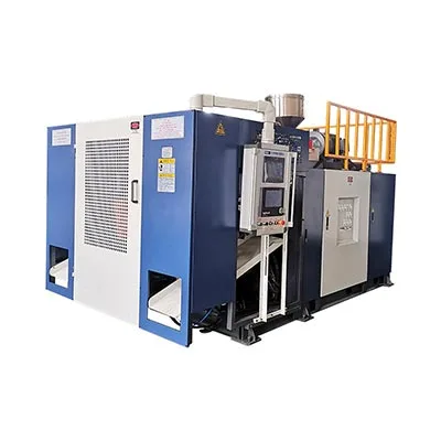
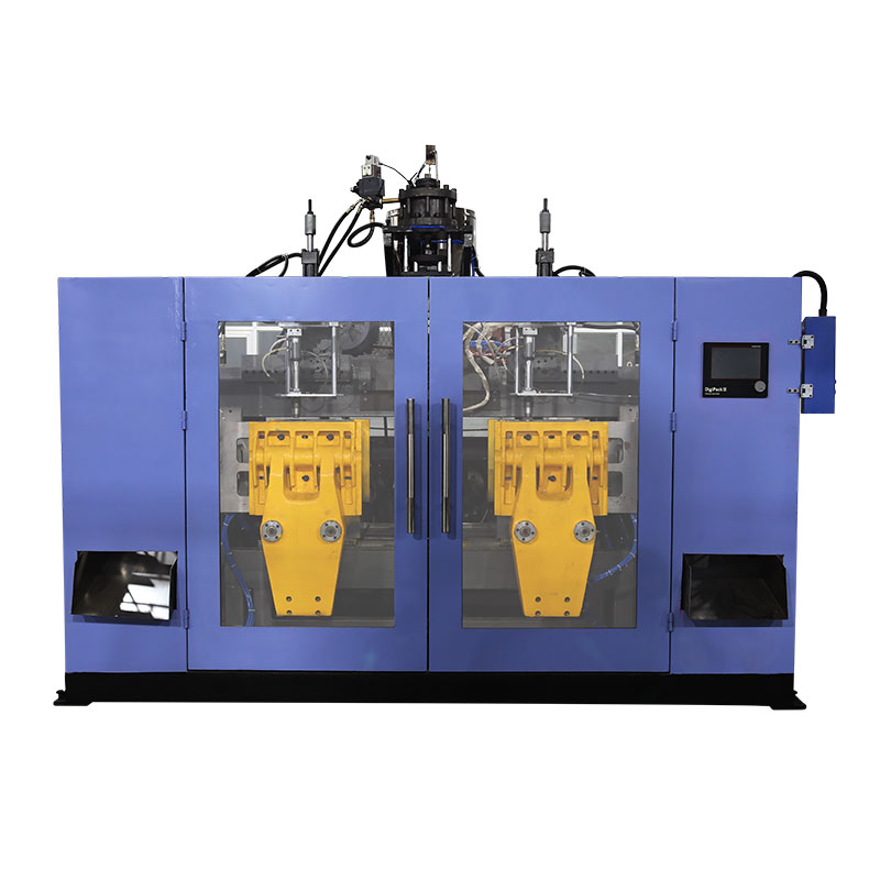
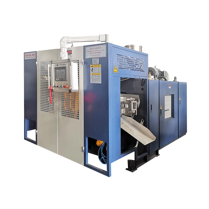
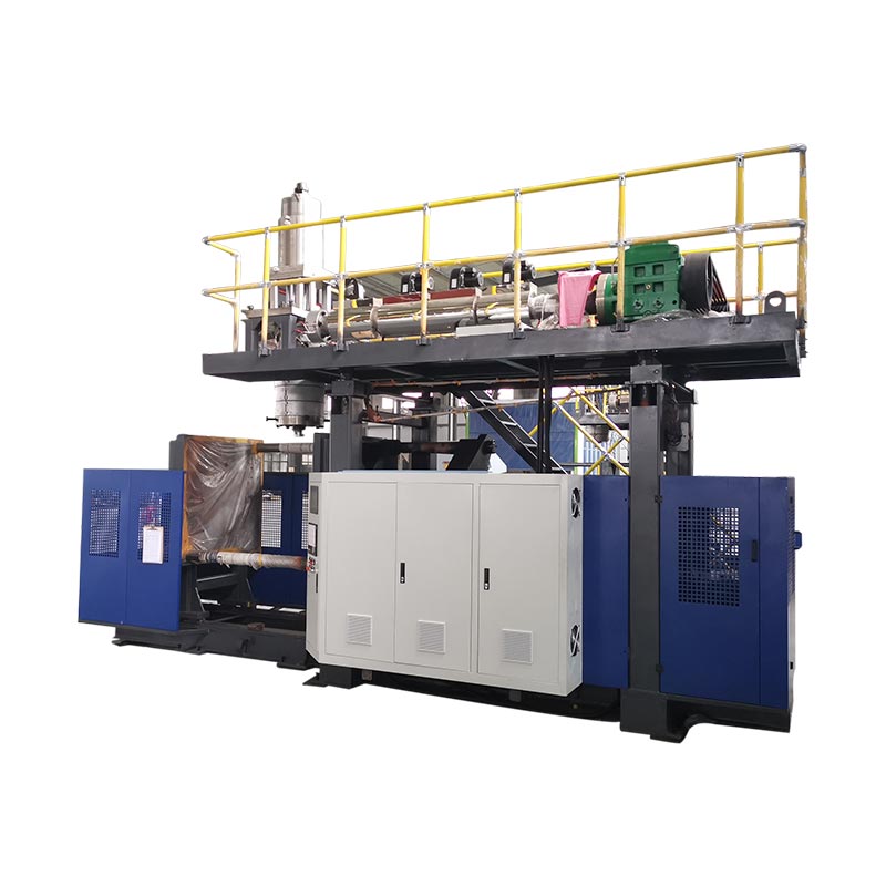
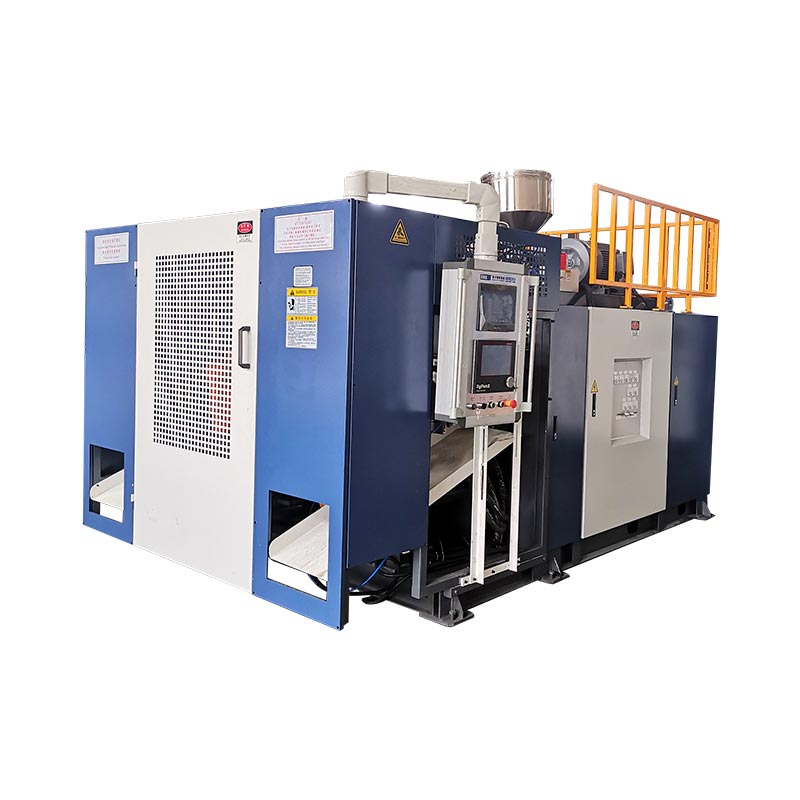
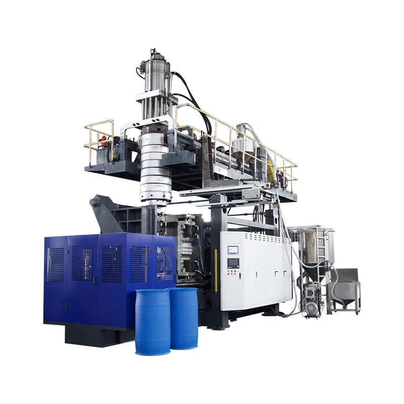
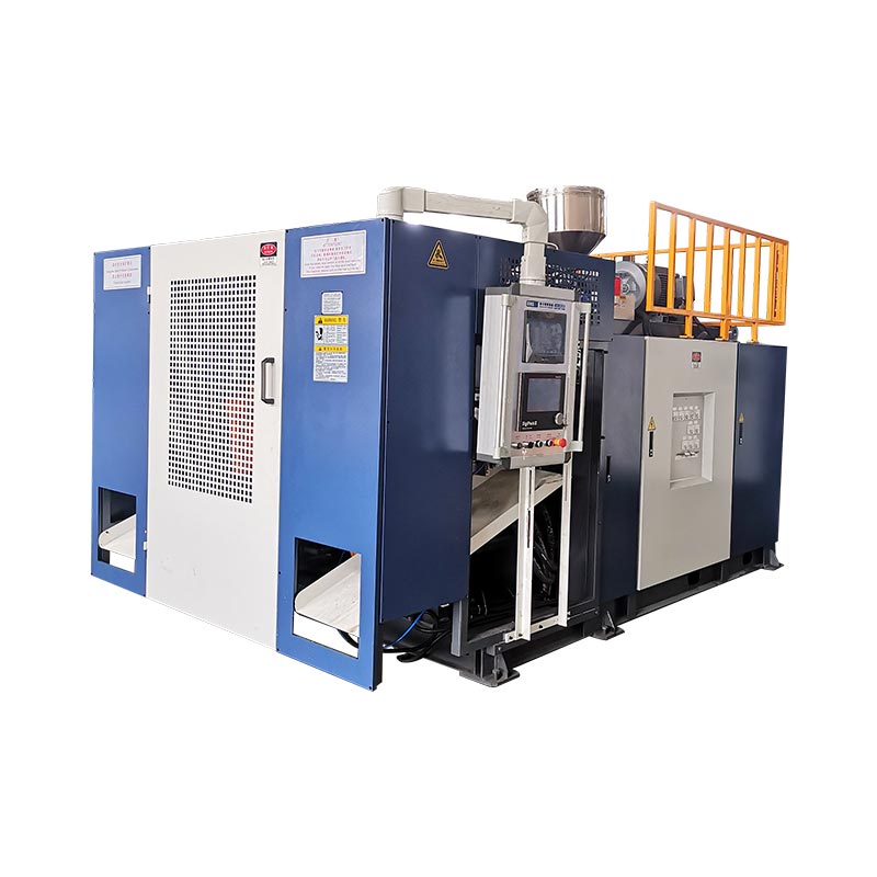
The KGB5L and KGB5D provide relevant continuous extrusion bottle-machine examples. Their published station layouts help organize inspection records: preserve station identity and, where applicable, head and cavity identity. The catalogue does not identify a universal blow pin for every bottle produced on either platform.
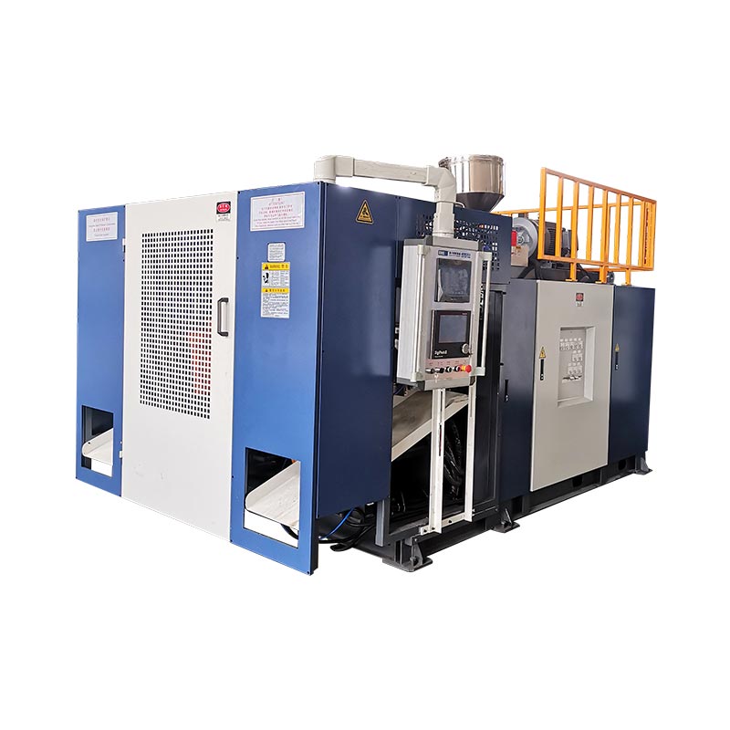
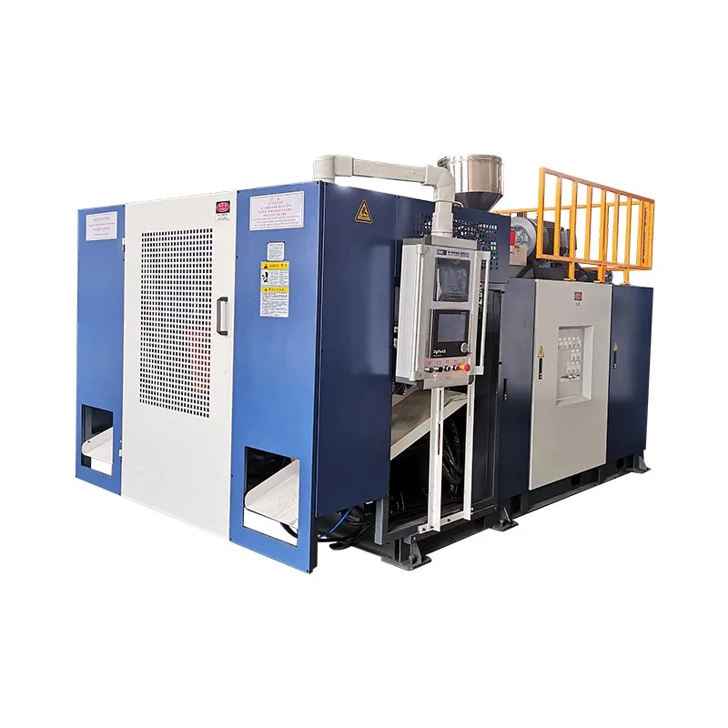
| Published field | KGB5L | KGB5D |
|---|---|---|
| Station arrangement | Single | Double |
| Maximum container capacity | 5 L | 5 L |
| Screw diameter | 60 mm | 70 mm |
| HDPE melting capacity | 55 kg/h | 80 kg/h |
Sources: the linked KGB5L and KGB5D product pages. Melting capacity is a published material-throughput field, not an accepted-bottle rate or a neck-quality result.
Use those figures to identify the platform and frame a production discussion. Blow-pin selection still depends on the bottle finish, mold, mounting and actual blowing arrangement. The die-pin diameter listed in a die-head specification is not a substitute for a blow-pin drawing.
For a new machine project, provide the bottle and closure drawings before approving the tooling scope. For an existing installation, add the current assembly identification and inspection evidence. The HDPE bottle-machine selection guide covers the broader production specification.
Frequently asked questions about blow pins and neck defects
Is a blow pin the same as a die pin?
No. A die pin or mandrel is part of the melt-forming tooling. A blow pin delivers blowing air and may have neck-related duties in the particular design. Identify either component from its assembly drawing. The shared word "pin" does not make their interfaces or dimensions interchangeable.
Does every extrusion blow molding machine use the same blow-pin design?
No. Blowing and finishing arrangements depend on the product and tooling. Calibration, cooling and cutting features are configuration specific. Confirm the actual assembly and movement before selecting a replacement or applying a setup instruction from another machine. Container volume alone cannot identify the correct component.
Can a bottle leak when the blow pin is in good condition?
Yes. Investigate the full bottle-and-closure interface, including the specified cap, sealing contact and test arrangement. Determine whether damage appears during molding or later handling. A leakage result identifies a failed check; it does not by itself identify which tool, component or process condition caused the failure.
What information is needed to review a replacement blow pin?
Provide the machine model and serial number, mold identity, blow-pin assembly drawing and revision. Add the mating neck tooling and relevant bottle-and-closure drawings. For a defect investigation, include sample identity, photographs, measurements and the sequence in which the problem first appears. Use the approved contact channel for technical documents.
What should be checked after a blow pin is repaired or replaced?
Confirm assembly identity and setup against the approved documents, then inspect the affected neck features under the agreed measurement conditions. Repeat the relevant package test with the specified closure. Record quantities and failures, keep the revised setup, and follow the quality plan for continued checks and production release.
Send the machine, tooling and neck-defect details
Start with the model and serial number, tooling identification and a marked defect photograph. Include the bottle-and-closure requirements, the first affected production stage and any measured results. These details give the technical discussion a defined starting point.
Discuss the tooling and production requirementNingbo Kinggle Machinery Co., Ltd. · Company information