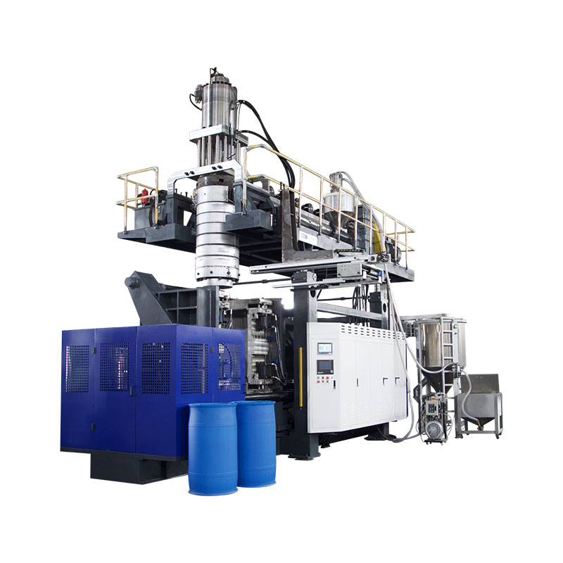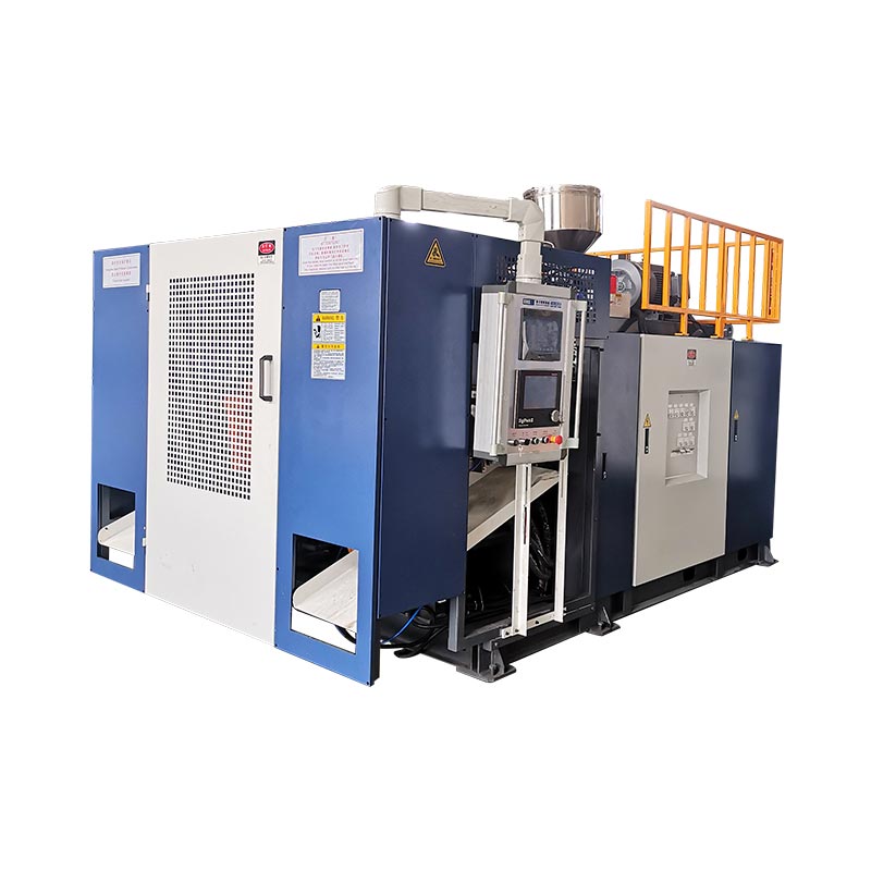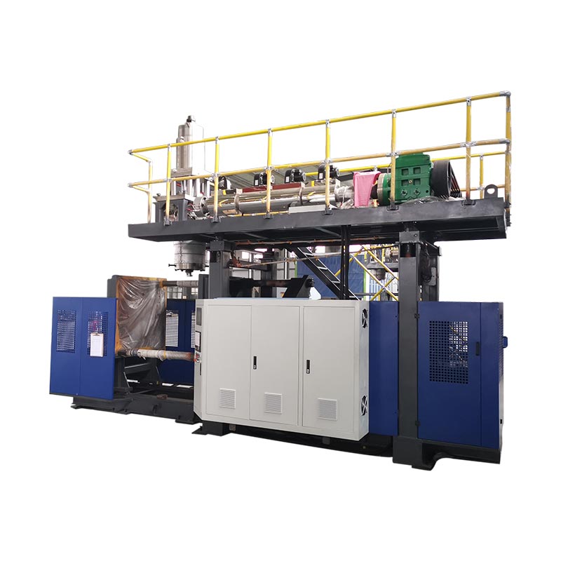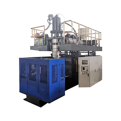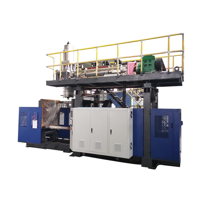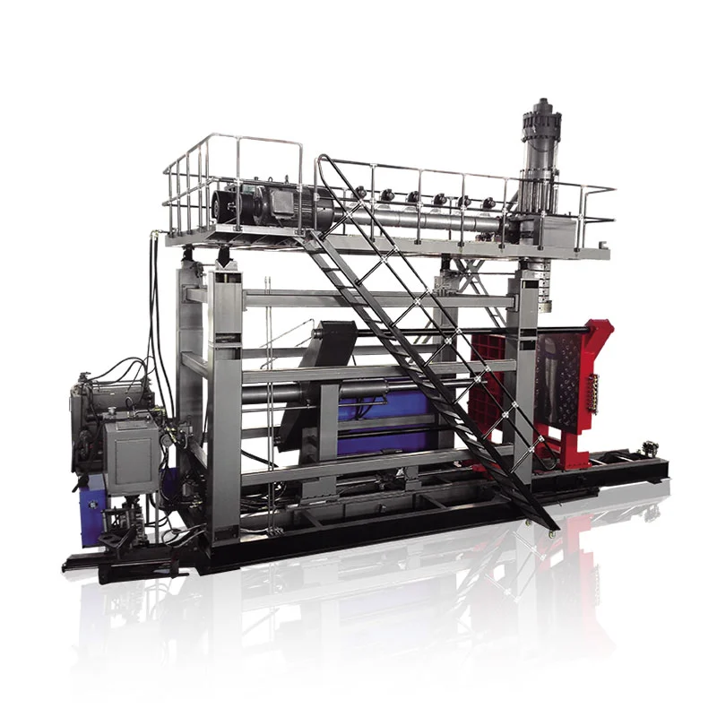
The most useful blow molding energy metric is not installed power or one momentary kW reading, because neither shows how much saleable production came from the energy consumed under stable, specified production conditions. Use electricity measured during a stable production window, divide it by accepted output from the same timed window, and record the boundary, meter positions, product, mold, resin, cycle and quality rules. For a full operating-cost view, measure the blow molding machine first, then add allocated compressed-air, cooling, material-handling, scrap-handling and downstream loads when they sit outside the main machine meter, without counting the same energy twice.
The five numbers worth putting on one report
- Machine electricity during the test, in kWh
- Average active power during the same window, in kW
- Extruded mass and accepted product mass
- Accepted parts made during the test
- Allocated air, cooling and downstream energy
| Measurement view | Typical boundary | Best denominator | Question it answers |
|---|---|---|---|
| Connected load | Installed motors, heaters, controls and selected auxiliaries | None | How should electrical infrastructure be sized? |
| Main-machine energy | Incoming supply to the blow molding machine | kg extruded, accepted kg or accepted parts | What does this machine consume under a defined run? |
| Product-related energy | Defined machine boundary, mold and specified product | kg of measured production | How can two product trials be compared? |
| Full-line energy | Machine plus allocated compressor, chiller and line equipment | accepted kg or accepted parts | What electricity belongs in the product-cost model? |
Start by drawing the energy boundary
“How much power does a blow molding machine use?” sounds simple. It is not one measurement. The answer changes with the line drawn around the equipment. A main incoming meter may include the extruder, heaters, hydraulic system, clamps, controls and attached robot. It may exclude the central air compressor and chiller. Another plant may place local cooling equipment inside the machine panel. Those readings cannot be compared until the boundary is stated.
The official EUROMAP recommendations list separates this problem into two documents for blow molding machines. EUROMAP 46.1 addresses machine-related energy efficiency. EUROMAP 46.2 addresses energy used to make a specified product with a given mold. Both documents are Version 1.0 from January 2014. They remain listed on EUROMAP's current technical-recommendations page.
That distinction is useful in a factory. A standardized machine test can describe machine behavior under stated conditions. A product test answers a different commercial question. It shows the energy used while making a defined container, part or tank. Neither reading automatically includes the complete plant. The compressor room, cooling plant, resin system, grinder, conveyor, trimmer and leak tester may sit outside the machine meter.
Draw a simple one-line diagram before installing meters. Mark the incoming machine supply. Mark each auxiliary supply. Then list central services that cross the boundary. Record any load shared by other lines. A shared compressor cannot be assigned entirely to one blow molder. A chiller serving five machines also needs an allocation method.
Use energy per kilogram and energy per accepted part
Average power and energy are related, but they are not interchangeable. Kilowatts describe a rate of use. Kilowatt-hours describe energy consumed over time. EUROMAP 46.1 defines total machine energy as mean active power multiplied by the measurement interval. It defines specific energy consumption as that energy divided by the extruded mass during the same interval.
The kWh/kg value is valuable for process and machine comparison. It normalizes different run lengths. It also handles parts of different size better than kWh per cycle. Still, extruded mass includes material that may not become accepted product. Flash, tails, startup purge, rejected containers and test pieces can change the business result.
Add a second metric for factory costing. Divide the relevant line energy by accepted parts or accepted mass. Use the unit that matches how the product is sold and controlled. A bottle producer may prefer kWh per 1,000 accepted bottles. A large industrial-part producer may prefer kWh per accepted part. A material-focused team may choose kWh per accepted kilogram.
Keep both denominators. The gap between extruded mass and accepted mass exposes yield loss. A process can show a good machine kWh/kg result yet waste energy through rejects. Another process may use slightly more power but produce more accepted parts in the same period. One reading alone cannot show that tradeoff.
Do not use connected load as a consumption result. Connected load helps size transformers, cables and protective devices. Actual operating energy depends on the cycle, resin, mold, control strategy and production state. Kinggle's utility-planning guide explains this difference for factory preparation.
Measure only after the process becomes stable
A short meter reading taken during warm-up does not describe production. Barrel heaters may be working differently from their steady pattern. Hydraulic oil may still be changing temperature. Operators may be correcting parison length or removing startup parts. The denominator is also weak because few accepted products have been counted.
EUROMAP 46.2 gives a specific product-test method. The product must meet customer requirements. The machine must run automatically without manual intervention for at least 15 minutes. The barrel must have remained at set-point temperature for at least 15 minutes. A hydraulic machine must also reach stable oil temperature and hold it for at least 15 minutes.
The formal measurement then lasts at least 10 minutes and covers at least 15 cycles. The collected product mass is weighed. EUROMAP also calls for instrumentation certified to the referenced IEC 62053-22:2003 meter classes. These conditions belong to that recommendation. A plant can choose a longer window when normal variation, multiple stations or downstream events need more coverage.
| Before the timed window | During the window | After the window |
|---|---|---|
| Confirm the approved product, mold, material and recipe | Keep meter and output timestamps aligned | Weigh the defined production mass |
| Reach stable automatic production | Record alarms, stops and manual actions | Count accepted parts and rejects |
| Confirm thermal and utility conditions | Do not change process settings | Complete the required quality checks |
| Zero or record every relevant meter | Observe all stations, heads and cavities | Save recipe, meter and inspection records |
EUROMAP 46.2 also identifies documentation needed for comparison. It includes machine identity, installed power, screw details, barrel insulation, part weight, wall thickness, material and supplier. Cycle details, clamping information, temperatures, measurement time, cycle count and average power factor also belong in the record. This level of detail keeps the result tied to the run that produced it.
For routine factory work, build a repeatable test sheet from these ideas. Mark any departure from the EUROMAP method. Do not call an informal check a EUROMAP test if the conditions and instruments were different. It can still be useful internal data when its method is clear.
Find which machine loads are consuming electricity
A whole-machine meter tells the size of the problem. It does not identify the cause. The main consumers usually belong to a few physical systems. The extruder drive moves and plasticizes material. Barrel and head heaters control the thermal state. The forming system powers clamp and station motion. Controls, fans, pumps and local cooling devices add smaller or intermittent loads.
EUROMAP 46.1 provides optional subsystem measurements for this reason. It separates the extruder motor and drive from barrel and head thermoregulation. It also defines forming-system energy. The recommendation includes additions for liquid cooling and accumulator-head energy when those systems apply. These categories offer a useful diagnostic map even when a plant is not running the formal classification test.
Start with a time plot, not one average number. Match power changes to real machine events. A steady extruder load has a different cause from a sharp clamp-motion peak. Heater cycling should be viewed beside zone temperatures. A hydraulic system may draw power while the machine waits. An attached grinder may start only after a flash batch reaches it.
The next step depends on the pattern. Rising extrusion load can justify checks for material state, screw condition or mechanical resistance. Excessive heater activity can point toward thermal losses, control behavior or an unstable process. Continuous pump demand during waiting needs a different investigation. The preventive-maintenance checklist helps separate energy symptoms from wear, leakage, cooling restrictions and poor condition.
Do not adjust several systems at once. Save the stable baseline first. Change one evidenced cause. Then repeat the same product test. This protects the link between action and result. It also shows whether lower machine power caused another loss, such as longer cycle time or poorer melt stability.
Add compressed air and cooling at the plant boundary
The machine's electrical meter may miss two important factory loads. Blow air is produced elsewhere in many plants. Cooling water may come from a central chiller and pump set. Neither utility is free. Both must be measured or allocated before the factory can estimate full-line electricity per accepted part.
For compressed air, record pressure and flow at the machine during production. Pressure alone is not a quantity of air. Flow alone does not reveal the delivered condition. Note the operating period, receiver behavior, dryer arrangement and other users on the header. Leaks and inappropriate uses can also distort the plant total.
The U.S. Department of Energy maintains a compressed-air systems resource with guidance on analysis, controls, storage, pressure, leaks and system costing. Its MEASUR platform also includes calculators for compressed air, motors, pumps and other plant systems. These tools can support an assessment. The actual compressor performance and measured system data must still drive the allocation.
For cooling, define what the meter covers. A local chiller can be metered directly with its pumps. A central plant needs a transparent method based on measured electrical energy and the line's assigned load. Supply and return temperatures, flow, ambient conditions and simultaneous users may matter. Do not convert cooling-water flow into electrical energy with a generic factor.
Kinggle's blow molding utility guide recommends separate metering for reliable product-cost data. It also notes that a whole-line meter can include the compressor, chiller, grinder, conveyor and downstream equipment. Use that approach when the plant layout allows it. Otherwise, keep each allocation formula visible.
Connect energy with cycle time, part weight and rejects
Energy efficiency is a production result. The lowest momentary kW does not always create the lowest kWh per accepted part. A machine may draw more power while moving, yet finish more acceptable products in an hour. Another setting may reduce average power but extend the cycle. The denominator decides which result matters.
Cycle time is the first connection to check. Use the method in Kinggle's cycle-time optimization guide. Measure the limiting step, then compare accepted output. A shorter timer is not a saving if it causes hotter parts, dimensional drift or downstream congestion. Record both average power and measured energy across the same production window.
Part weight and wall distribution also affect the energy result. More material requires plasticizing and heat removal. Yet a lower total weight is not automatically acceptable. Critical walls must still meet the product requirement. Use the parison programming guide to connect profile changes with measured wall locations. Use the mold design guide when a local cooling limit comes from the tool.
Rejects deserve their own line on the energy sheet. Electricity used for a rejected part has already been consumed. Some material may be recovered, but the machine time, air and cooling are not recovered. Track startup purge, flash, tails, visual rejects and functional-test rejects separately. Kinggle's defect troubleshooting guide helps link common faults to process evidence.
Changeovers and starts can dominate short orders. Heating, purging, color transition and first-off approval consume energy before saleable output begins. Use the startup checklist and changeover guide to record that loss. Report steady-state energy and order-level energy separately. Each answers a valid but different question.
Compare servo hydraulic and other drive systems fairly
Drive labels can help a buyer understand architecture. They cannot replace a product test. A servo hydraulic machine, conventional hydraulic machine and electrically driven design may manage idle periods differently. Their results also depend on clamp movement, extruder duty, accumulator operation, pump sizing, controls and required production pace.
Begin with the same product. Keep the mold, material, part weight, wall requirement and acceptance tests comparable. Include the same auxiliary boundary. Then run each machine at a stable approved process. A comparison made with one machine in dry cycle and another making finished parts has little commercial value.
Look at the power trace as well as the final kWh. Dynamic loads may rise during mold motion or accumulator push-out. Idle demand may matter when the sequence contains waiting. Extrusion and heating can dominate another job. On a multi-head machine, the useful output per event changes again. The multi-head and multi-cavity guide explains why parts per cycle must be defined.
Machine layout can also change the denominator. A single-station or double-station line may overlap extrusion, cooling and part handling in a different way. That does not guarantee one energy result. The product, cycle balance, cooling capacity and downstream line determine accepted output.
Ask suppliers to state the test boundary and conditions. Request machine energy, accepted output, extruded mass and quality evidence from the same interval. If a percentage-saving claim is offered, ask for both original measurements. Also ask what equipment sat outside each meter. This turns a drive-system claim into a comparison that engineering and purchasing can review.
Run an eight-step plant energy test
The plant does not need a complicated dashboard to begin. It needs a controlled test, suitable meters and a clear output count. Qualified electrical personnel should install or connect instruments under the plant's safety procedures. Production and quality staff should approve the product conditions before the timed run.
- Define the product and acceptance rule. Record the drawing, part revision, mold, resin, color, regrind rule, target weight and required checks. State which parts count as accepted.
- Draw the meter boundary. Mark the main machine, local auxiliaries, compressor allocation, cooling allocation and downstream loads. Give every meter a name.
- Check instruments and timestamps. Use meters suitable for the measurement. Align the clocks used for electricity, machine cycles and production counts.
- Reach stable automatic production. Confirm thermal state, utilities and quality. For an EUROMAP 46.2 test, follow its stated stability and instrumentation requirements.
- Measure without changing the recipe. Record start values, end values and the production window. Note alarms, stops, manual interventions and unusual utility events.
- Count mass and accepted output. Weigh the defined production mass. Count accepted parts, rejects, flash, tails and other excluded material using clear categories.
- Calculate the paired metrics. Report machine kWh/kg and energy per accepted part or accepted kilogram. Add plant utilities only through the documented allocation.
- Repeat one controlled change. Fix an evidenced loss, restore stable conditions and repeat the same test. Keep the new setting only when quality and safety remain approved.
Save the raw data. A final ratio is not enough for later troubleshooting. Store meter readings, cycle counts, part weights, inspection results, recipe revision and photographs of meter locations. If the power trace is available, keep it with the machine-event log.
Review the result with more than one department. Maintenance can explain pump, heater and cooling behavior. Production can explain waiting and short stops. Quality defines the accepted denominator. Purchasing needs a result that can be placed into a cost model. A shared report prevents one team from improving its number while moving the loss elsewhere.
Use the HMI and alarm guide to separate commands from actual machine states. Use the factory acceptance test guide when the test supports a machine purchase. Energy evidence should sit beside product-quality and output evidence, not replace them.
Schedule a repeat check after the process has returned to normal production. A one-day result can be affected by maintenance condition, ambient temperature or a temporary utility problem. Trending the same product and boundary shows whether the gain remains real. It also gives the factory an early signal when energy per accepted part begins to drift.
Turn energy consumption into a purchasing question
A useful quotation starts with the product, not a general efficiency adjective. Kinggle's current sales process asks buyers for product photos or drawings, weight, size, material, thickness, output and chemical-resistance needs. Those inputs also define a meaningful energy discussion.
Ask for connected load and expected operating data separately. Connected load supports the electrical design. A product-related test supports the production-cost estimate. Request the meter boundary, test duration, machine condition, mold, resin, gross extruded mass, accepted output and quality checks. State whether compressed air and cooling are included.
For a new project, agree on the test before the machine trial. Choose the product and material. Freeze the acceptance criteria. Identify who supplies the meter and who verifies the counts. Decide how startup, rejects, flash and recycled material will be treated. If EUROMAP 46.2 is the agreed method, name it in the test plan and follow its conditions.
Use the result as one part of total cost. Electricity matters, but the machine must still make the required product. Review output stability, yield, changeover loss, maintenance access, spares, labor and downstream compatibility. One weak assumption can outweigh a small difference in steady-state kWh.
Kinggle supplies both continuous extrusion blow molding machines and accumulator blow molding machines. The appropriate measurement plan depends on the selected configuration and product. Send the product drawing and factory utility information before requesting a project estimate.
Frequently asked questions
How much electricity does an extrusion blow molding machine use?
There is no reliable universal figure. Consumption changes with machine configuration, extruder size, drive system, heaters, product, mold, resin, cycle and included auxiliaries. Measure kWh during a stable production window. Divide it by extruded mass and accepted output. Keep connected load separate because it is used for electrical-system sizing, not product-energy costing.
What is the best energy-efficiency metric for blow molding?
Use at least two metrics. Machine kWh per kilogram of extruded mass supports technical comparison. Full-line kWh per accepted part or accepted kilogram supports product costing. Report average kW and total kWh as supporting data. Every result should identify the product, mold, material, quality rules and meter boundary.
Does installed power show normal machine consumption?
No. Installed or connected power helps engineers size transformers, cables, breakers and isolation equipment. Not every load runs at full rating throughout production. Actual energy depends on time and operating state. Use a suitable energy meter during stable production instead of estimating electricity from the nameplate alone.
Should compressor and chiller power be included?
Include them when calculating full-line energy or product cost. Keep them separate when reporting a main-machine measurement. Central systems need a documented allocation because they may serve several lines. Check the meter map first so local compressors, chillers or pumps are not counted twice.
Does a servo hydraulic blow molding machine always use less energy?
Do not decide from the drive label alone. Compare machines while making the same accepted product under equivalent conditions. Include the same auxiliaries and measure the same time window. Idle demand, clamp motion, extrusion, heating, accumulator duty and cycle balance can change the result for each application.
How can a factory reduce energy per accepted part?
Measure the current loss before changing settings. Common investigation areas include idle demand, air leaks, cooling restrictions, heater condition, hydraulic behavior, long cycle steps, rejects and changeover waste. Correct one evidenced cause, then repeat the same product test. Keep the change only when output, quality, safety and machine condition remain acceptable.
Need an energy test plan for your product?
Share the product drawing, material, target weight, output, mold information and available factory utilities. Kinggle can use those details to define the machine configuration and a measurable acceptance boundary.
Send Your Product RequirementsSources checked for this guide
- EUROMAP Technical Recommendations, current list showing EUROMAP 46.1 and 46.2 under Blow Moulding, checked September 9, 2026.
- EUROMAP 46.1, Version 1.0, January 2014, machine-related energy definitions and subsystem measurement.
- EUROMAP 46.2, Version 1.0, January 2014, product-related energy method, stable-run conditions and documentation.
- U.S. Department of Energy, Compressed Air Systems, system assessment and technical resources, checked September 9, 2026.
- U.S. Department of Energy, MEASUR, plant-system analysis tools, checked September 9, 2026.
- Kinggle, Blow Molding Machine Utility Requirements, machine and full-line utility boundary, checked September 9, 2026.
- Kinggle Sales Process, product information requested for project definition, checked September 9, 2026.