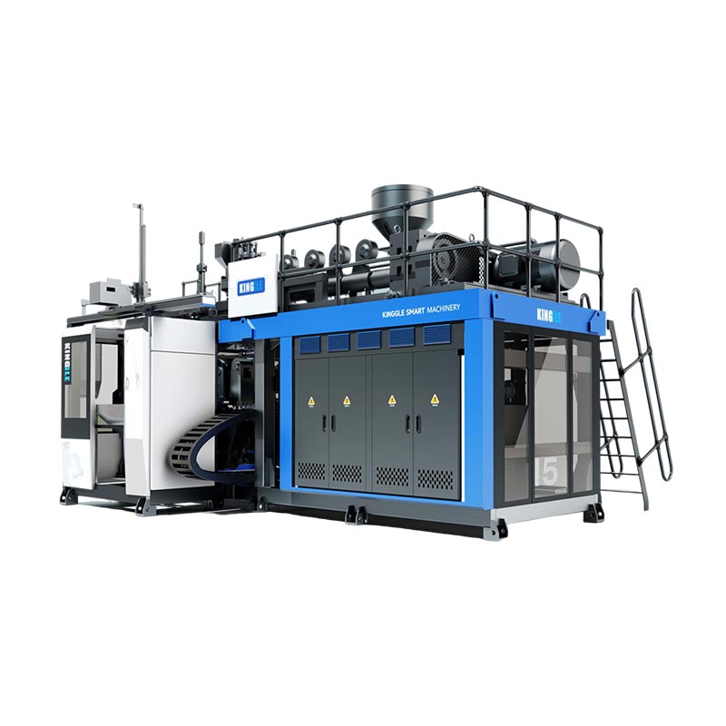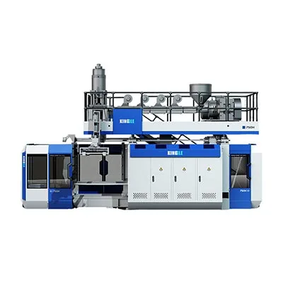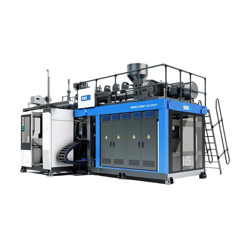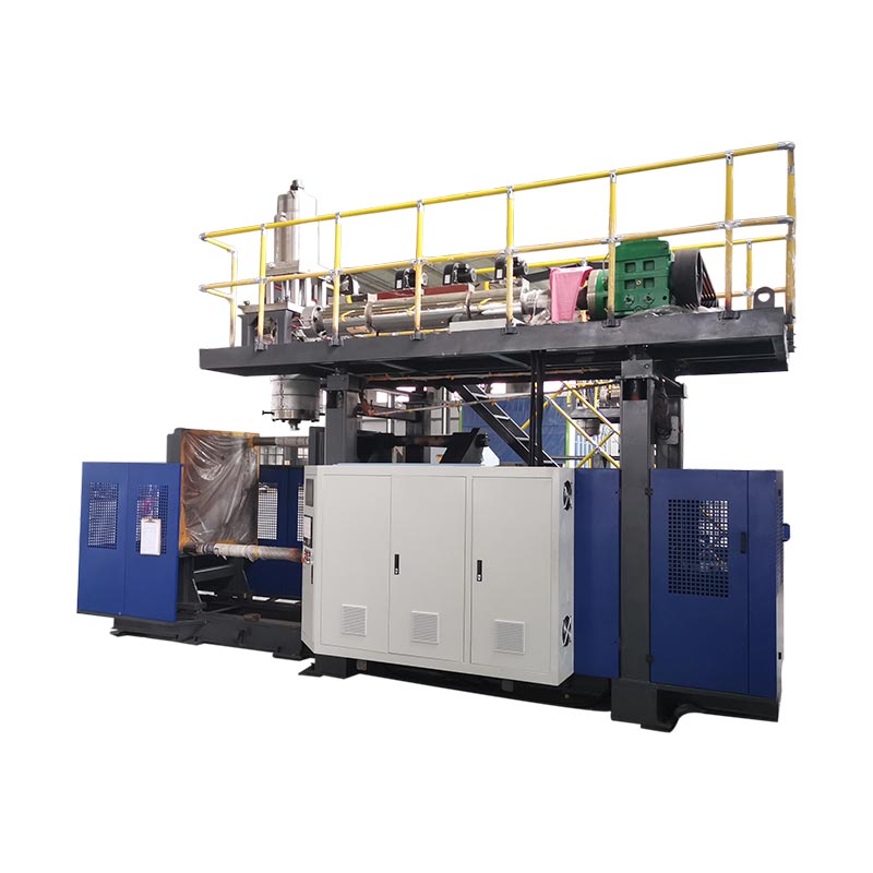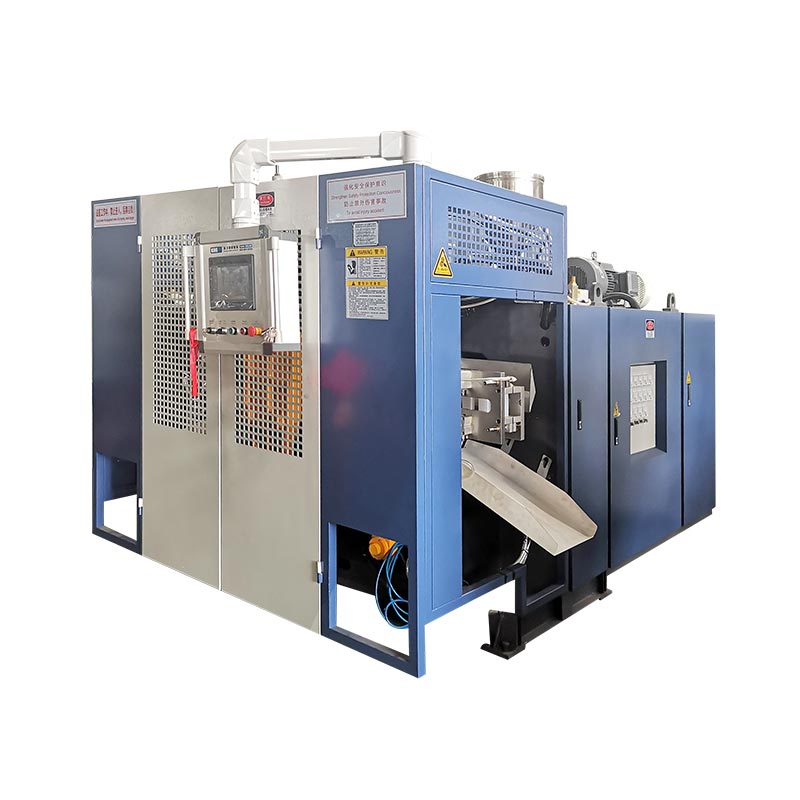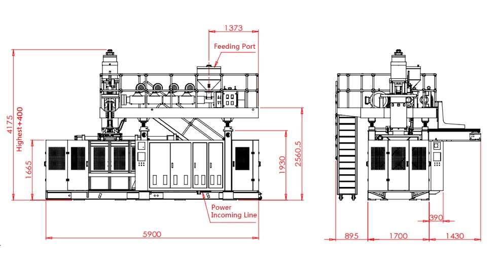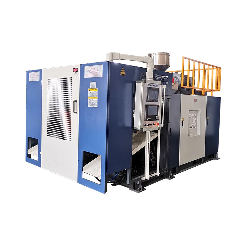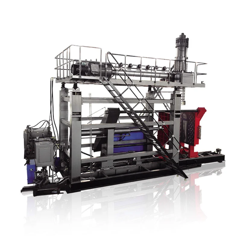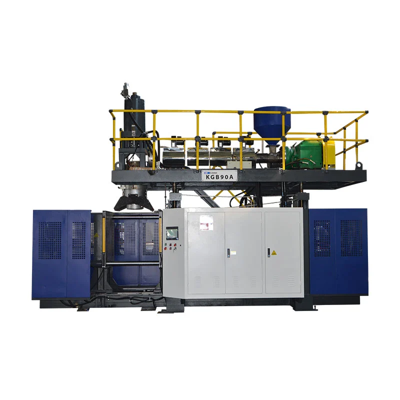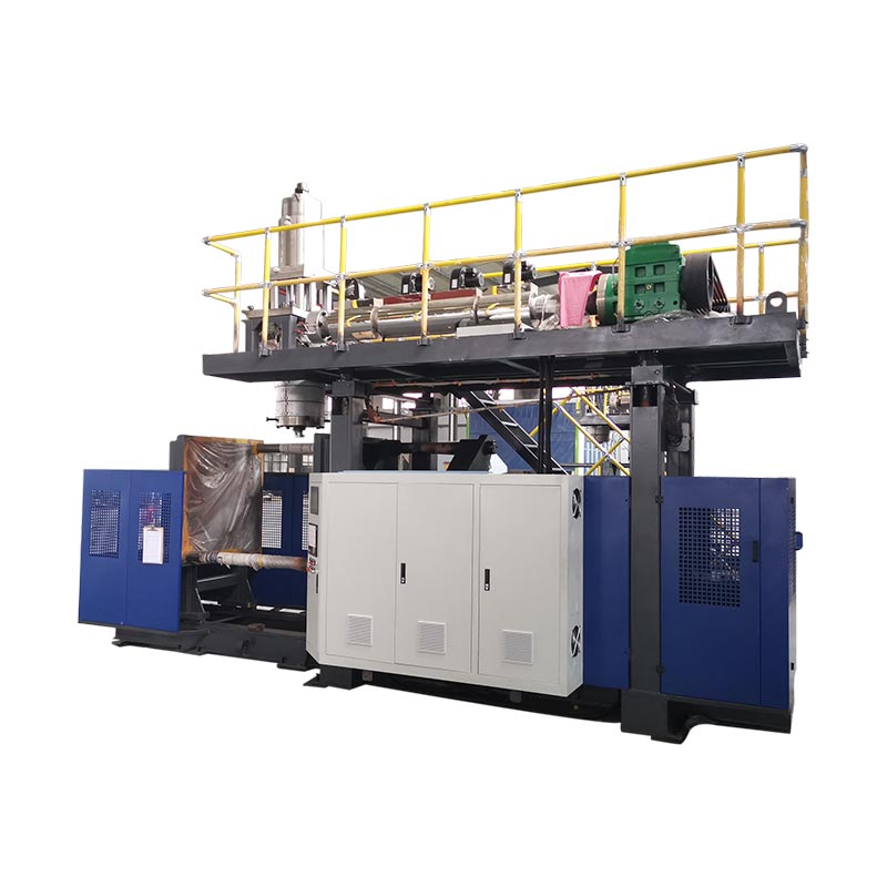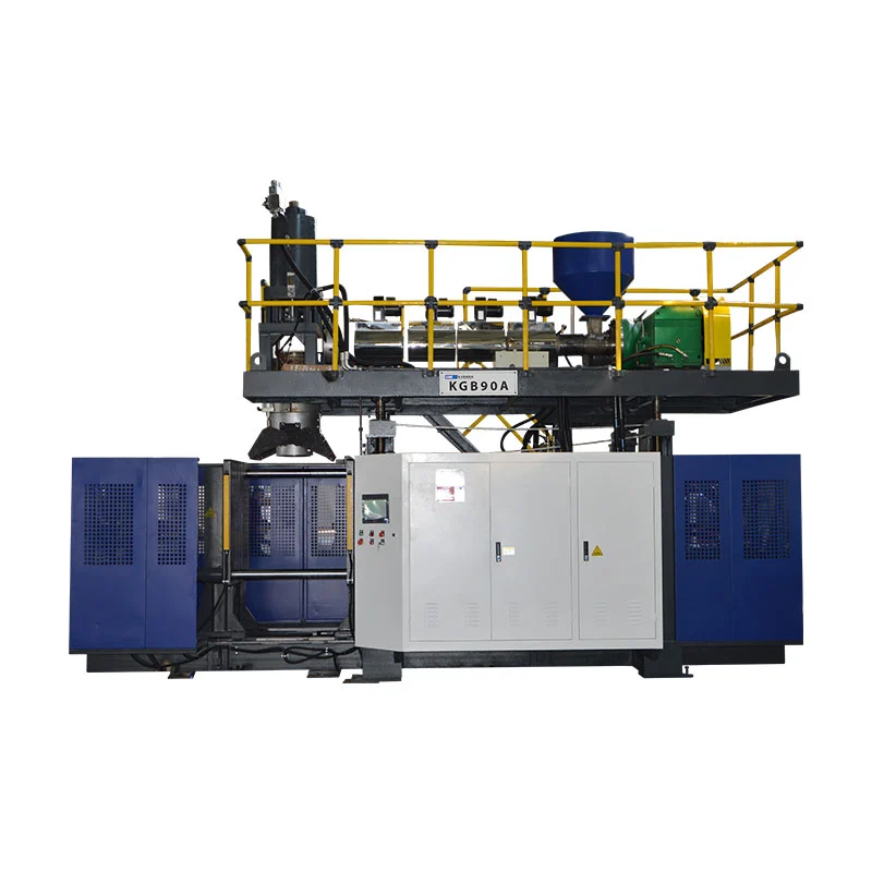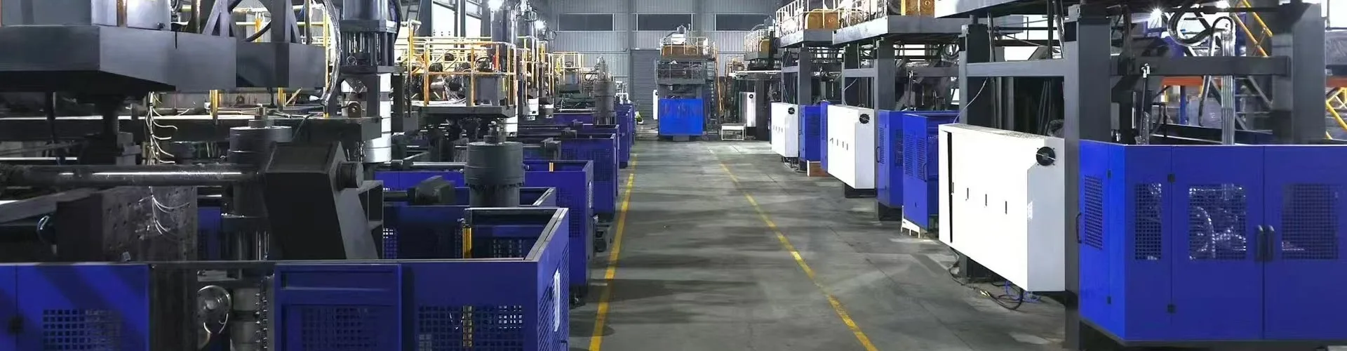
Check an extrusion blow molding machine against three conditions before you order it. The clamp must supply enough force during both parison pinch-off and inflation. The complete mold must fit the mounting interface. Once the mold opens, the part, attached flash and take-out equipment need a clear exit path.
A clamp rating in kilonewtons answers only part of that review. A two-cavity layout can double the inflation load on one clamp, while a thicker mold can leave less room for part removal. Use the same drawing revision, cavity sequence and pressure assumptions for all three checks.
What the Clamp Must Do During an Extrusion Blow Molding Cycle
The mold closes around a hot tube of plastic called a parison. Near the end of closing, the pinch-off lands squeeze the parison walls together where the tool must seal them. During inflation, the gas inside the parison pushes against the mold through the expanding plastic. The clamp must keep the mold closed under that separating load. The two demands occur at different points in a typical cycle, so review the available force at the relevant position and time for each demand. Extrusion blow molding clamp disclosure · Blow molding clamp assembly disclosure
Close the Mold and Seal the Parison
Ask the mold maker to identify the pinch-off lands and specify the material and parison conditions used for the review. The resistance at final closing depends on the pinch geometry and the amount and condition of plastic caught at the seam. A specification that gives only the holding force at full closure leaves the final closing requirement open. Confirm when pre-blow starts, if used, so that any overlap in loads can be evaluated against the proposed cycle. LyondellBasell polyolefin blow molding guide
How to Check for Insufficient Clamping Force
Extrusion blow molding can leave trim around the mold parting line and at the ends of the parison. Start with a trimmed part and its untrimmed sample from the same cavity. If the flash has changed, ask whether the mold faces moved apart during inflation and compare the closure and pressure records for that cycle. When the closure records show stable seating, check alignment, pinch-off condition and the parison at the seam. These checks help distinguish a holding-force problem from a tooling or material issue before anyone changes the clamp setting. LyondellBasell pinch-off and troubleshooting guidance
How to Estimate Mold-Opening Force
For an initial check under an approximately uniform pressure differential, multiply the pressure differential across the inflated parison by the effective pressurized area projected perpendicular to the clamp direction. In a conventional straight-opening mold, that is the parting-plane projection. Ask the toolmaker to mark the loaded area on the drawing, including any pressurized features. The outline of the mold block serves a separate purpose when checking mounting. Projected-area and blowing-pressure reference
Estimated opening force (kN) = pressure differential (MPa) × effective projected area (m²) × 1,000.
Use the Pressure at the Stage Being Checked
Record the pressure basis and when it applies. A plant air header, a blow-air regulator setting and the pressure inside the part describe different points in the air system. Hydraulic clamp pressure belongs to the clamp circuit. If the cavity pressure is still an estimate, identify it as such and ask the supplier how it will be confirmed during the trial.
Count Cavities That Load the Same Clamp at the Same Time
For cavities that inflate together on the same clamp, add the opening loads at the same point in the cycle. In a machine with separate clamps, calculate the load on each clamp from the cavities it holds. If the cavity layout is offset, supply the force locations as well as the total. The supplier needs the layout to assess load distribution, platen support and alignment under load. Kinggle guide to head and cavity layouts
How to Check Whether the Mold Can Be Mounted
Lay the mold assembly drawing over the machine interface drawing using the specified mounting faces and centerlines. Check support and fastener positions first. Then check the installed thickness, weight and service connections. A matching width and height can still leave a bolt pattern, centerline or clearance conflict.
- Mounting faces and support. Confirm usable platen area, mounting hole or slot locations, any guide or tie-bar obstruction, and the supported footprint of each mold half.
- Installed thickness and weight. Include mounting plates or spacers in the thickness between the platens. Give the supplier the assembled weight and center of gravity, including attached cylinders or other hardware.
- Tool and machine interfaces. Check die-head and parison centerlines, blow pin position and travel, water manifolds, hoses and moving connections. Use the full assembly envelope when checking interference.
Coordinate pinch-off, blow pin, cooling and vent details with the toolmaker on the same drawing revision. Extrusion blow molding mold design guide

Read the Catalog Fields Separately
The KGB90A specification lists 280 kN clamping force, a 960 × 980 mm platen and a 700 × 980 mm maximum mold size. It lists mold thickness from 460 to 550 mm. The page also has separate fields for Platen opening stroke and Platen moving stroke. Ask for the drawing that defines those dimensions and shows the open position with the proposed mold installed. KGB90A clamping unit specifications
How to Check Opening Travel and Part Removal
Opening stroke describes movement from one position to another. Open daylight describes the gap between specified faces in the open position. Read both dimensions from the machine drawing, then calculate the usable space between the installed mold halves. For a simple straight-opening arrangement with flat parting faces, subtract the installed closed mold thickness from the confirmed open distance between the same mounting faces.
Now trace the actual removal path. Include the molded part at take-out, any attached flash, the gripper and the movement needed to clear locating features. If a blow pin, slide or trimming device shares that space, check its position at the point in the cycle when the part passes it. Use the motion drawing to verify the narrowest point along the path. The maximum platen gap alone leaves those obstructions unaccounted for.
Worked Example With One and Two Cavities
Check Inflation Load and Cost per Accepted Cycle
In an illustrative extrusion blow molding setup for HDPE industrial drums, each cavity has a projected area of 0.18 m² on the mold parting plane. At an assumed uniform pressure differential of 0.60 MPa, the inflation load tending to separate the mold halves is 108 kN per cavity, or 216 kN when two cavities inflate simultaneously on the same clamp. A clamp that can deliver 200 kN at the closed position falls 16 kN short of the estimated load and may allow the mold to open during inflation. Check the force available during final closing separately, because sealing the hot parison depends on pinch-off geometry, wall thickness, and melt temperature. For two configurations that both meet the molding and part-removal requirements, a unit priced 25% higher must deliver 1.25 times as many cycles yielding conforming parts over its service life to match the purchase cost per accepted cycle. Blow mold clamping and pinch-off reference
For a comparison with different cavity counts or reject rates, use cost per accepted drum. Include maintenance and downtime if those costs differ between the two configurations. The 1.25 factor comes from the assumed purchase-price difference and applies to the simplified cost comparison above.
Check the Same Tool at Full Opening
Assume the closed tool stack measures 520 mm and the fully open distance between the mounting faces is 1,000 mm. With the flat geometry shown above, the available opening is 480 mm. If the motion drawing calls for 510 mm along the opening direction to remove the drum and gripper with the flash attached, the setup is 30 mm short. That clearance check still applies if a different clamp can meet the force requirement.
| Check | Calculation | Procurement decision |
|---|---|---|
| One cavity | 0.60 × 0.18 × 1,000 = 108 kN | Proceed to pinch-off, load distribution and available-force checks. |
| Two cavities on one clamp | 108 × 2 = 216 kN | The example's 200 kN available holding force leaves a 16 kN shortfall before any project allowance. |
| Removal clearance |
1,000 − 520 = 480 mm 510 − 480 = 30 mm |
Revise the opening or the take-out path and verify the revised assembly. |
What to Put on the Mold-Fit Review Sheet
Use one line per requirement and put the drawing revision or other evidence beside the supplier’s value. Treat a blank entry as an open item. The parties can then close each item before releasing the mold or accepting the equipment configuration.
| Item | Required input | Supplier confirmation | Evidence to attach |
|---|---|---|---|
| Inflation load | Projected area by cavity, assumed pressure and timing | Available holding force at the agreed mold position and the design allowance | Marked projection and pressure basis |
| Pinch-off | Seam layout, resin and parison condition at closing | Available force in the final closing range and the agreed cycle sequence | Pinch-off drawing and trial samples |
| Mounting | Tool stack, weight, center of gravity and fastening layout | Approved mounting positions, load support and thickness range | Mold assembly and machine interface drawings |
| Opening and removal | Part with flash, gripper and removal path | Open position and clearance through the full motion sequence | Motion drawing and trial record |
| Trial acceptance | Resin grade, tool revision and part requirements | Agreed trial sequence, inspection method and sign-off criteria | Samples by cavity and recorded cycle conditions |
At the trial, record the actual tool and material, confirm that the mold remains seated during inflation, inspect the pinch-off seam by cavity and observe the full part-removal sequence. Review machine safety against the requirements adopted for the project. ANSI/PLASTICS B151.31-2014 (R2020) covers blow molding machine safety. If a water-filled container drop test is part of the purchase specification, ASTM D2463-23 describes that test scope. Keep the machine safety review and the container acceptance criteria as separate entries on the trial plan. ANSI blow molding machine safety standard · ASTM container drop impact test · Kinggle factory acceptance test guide
Frequently Asked Questions
Can I select clamping force from container volume?
Use the container drawing to determine the pressurized projected area and confirm the inflation pressure for the proposed cycle. Containers with the same volume can have different projected areas. Check the force needed to seal the parison separately.
When should I add the forces from two cavities?
Add the opening loads when both cavities apply pressure to the same clamp at the same time. For separate clamps, calculate the demand on each clamp using its own cavity layout and pressure sequence.
What is the difference between platen size and maximum mold size?
Platen size describes the mounting plate dimensions. Maximum mold size is the machine supplier's stated tool envelope. Confirm usable support, fastening positions, the installed tool thickness and the clearances of the complete assembly on the machine drawing.
What is the difference between opening stroke and open daylight?
Opening stroke is travel between specified positions. Open daylight is the distance between defined faces when the clamp is open. Use the reference faces on the drawing and account for the installed mold before comparing the available opening with the take-out path.
Request a Mold-Fit Review
Send the part drawing, mold assembly drawing, cavity sequence, blow pressure basis and take-out layout to Kinggle. Include the machine model if the tool will move to an existing line. Contact Kinggle · sales@kinggle.com · +86-574-87103665
Before releasing the tool, get the supplier’s confirmation for the force at each relevant stage, the approved mounting arrangement and the demonstrated removal path. Record all three against the same mold drawing revision.