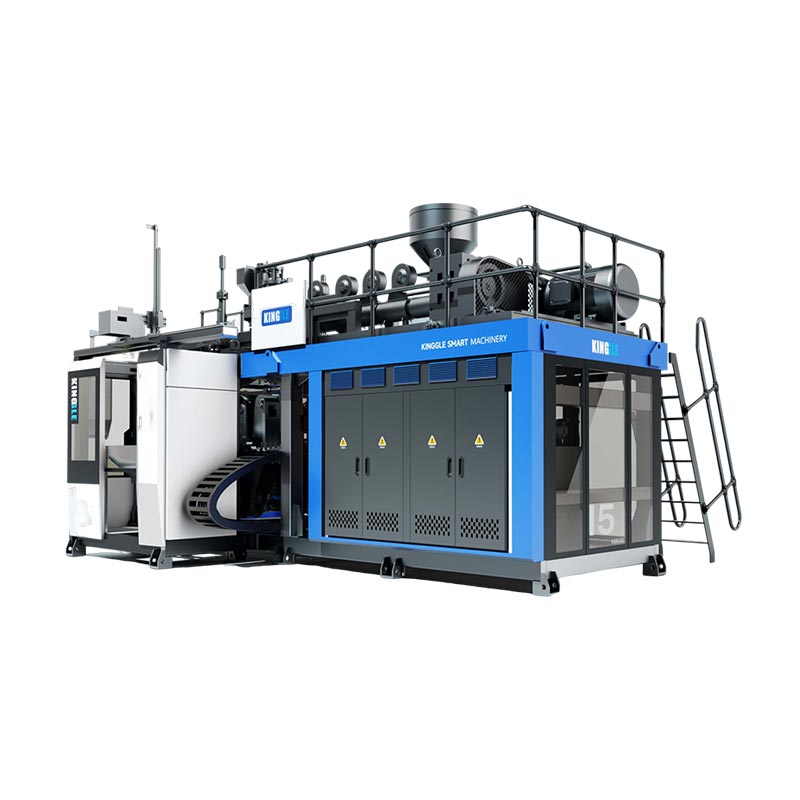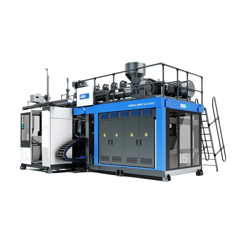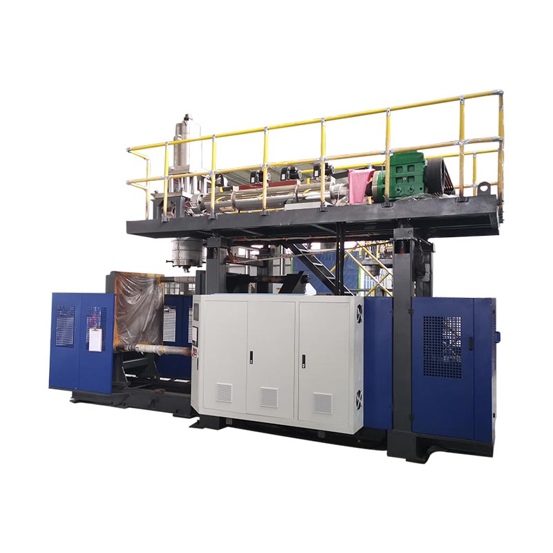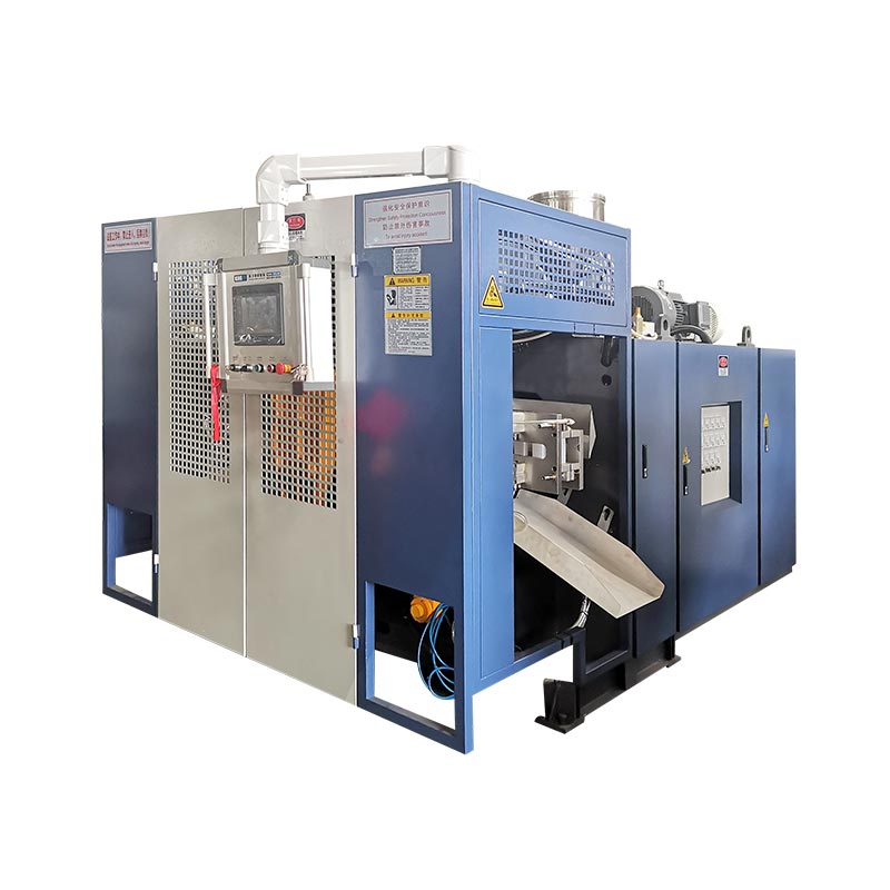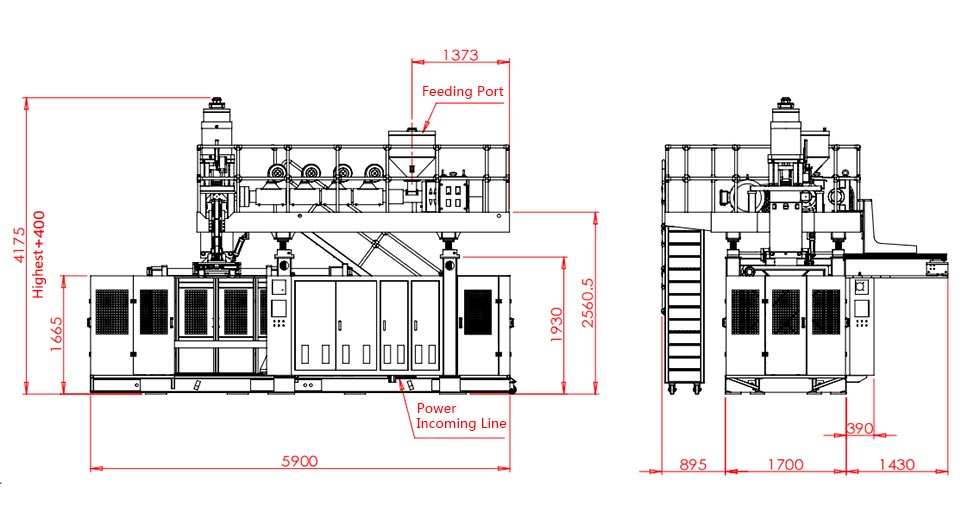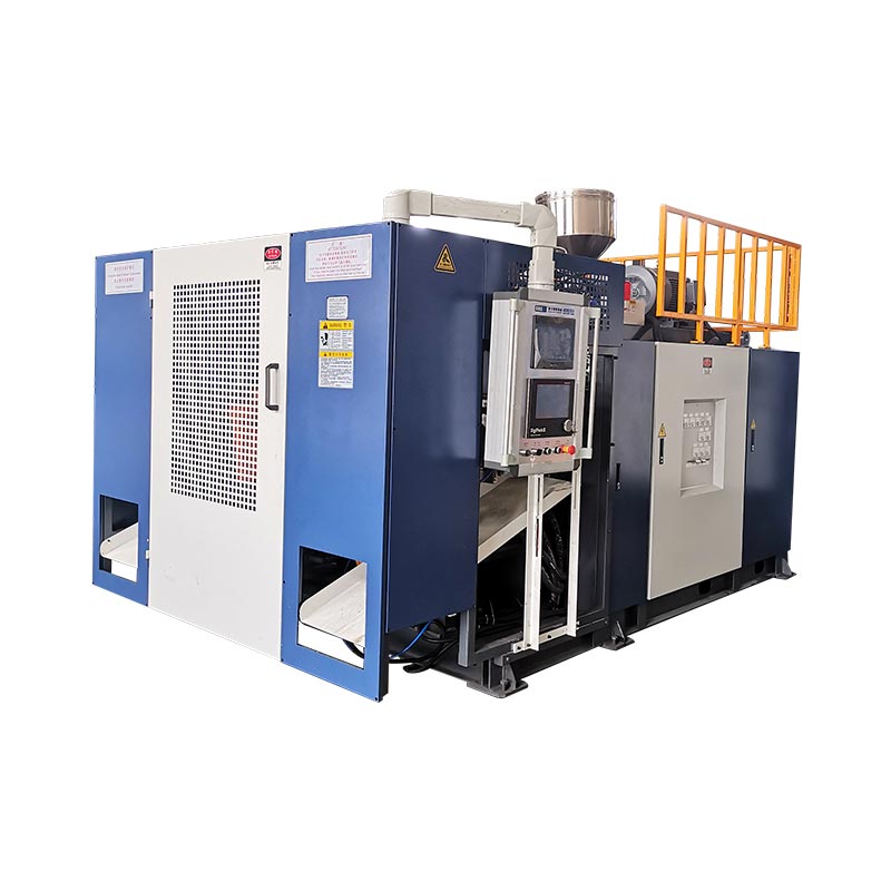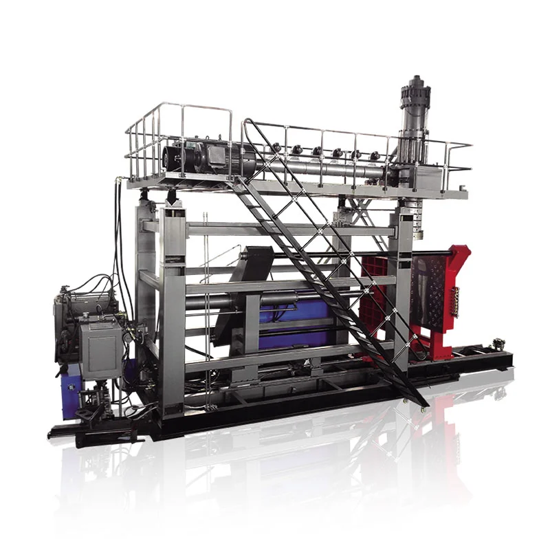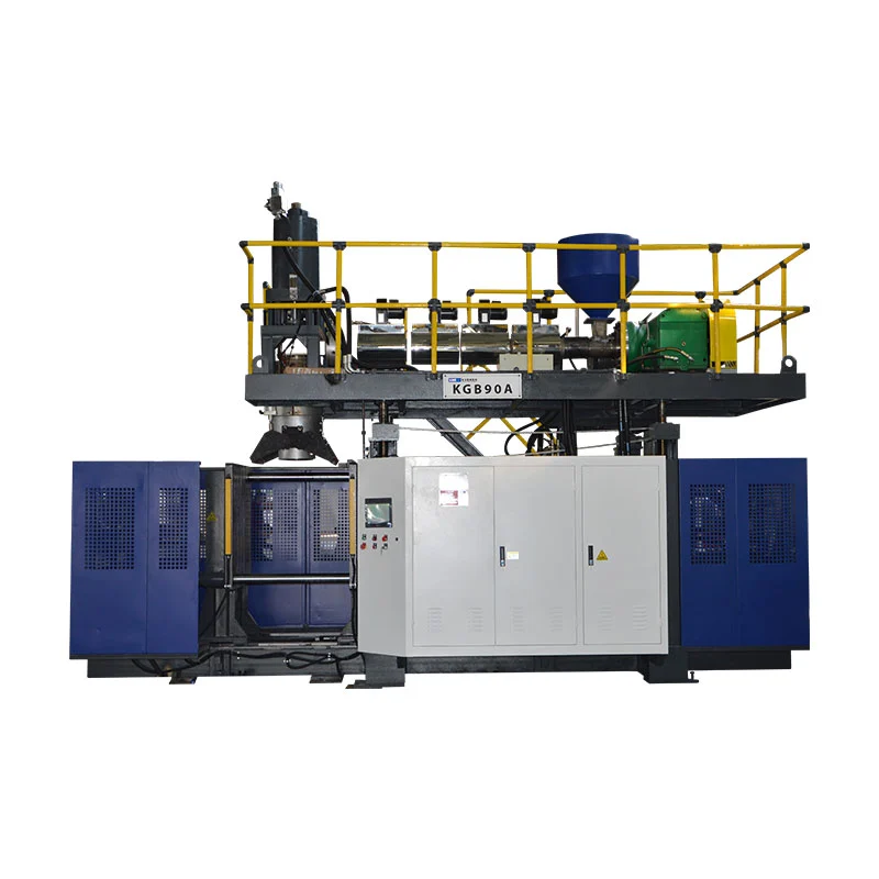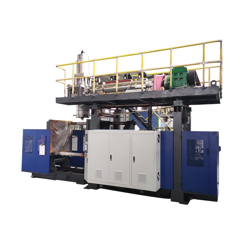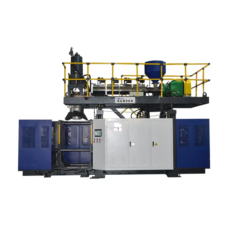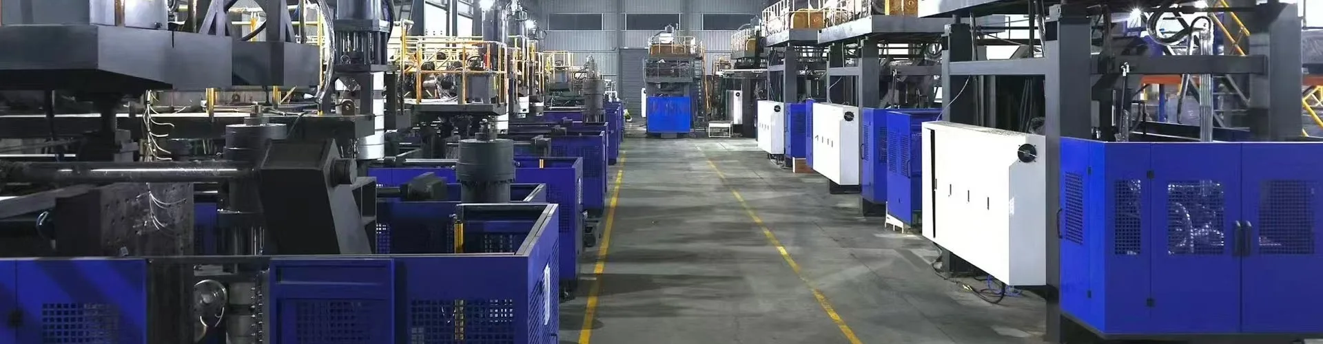
The extrusion blow molding process turns thermoplastic resin into hollow parts by extruding a hot tube, enclosing it in a mold, and inflating it with air. The part then cools, leaves the mold, and passes through trimming and inspection. Bottles, handled containers and larger industrial parts use this basic sequence, with different equipment layouts and finishing requirements.
For equipment selection, follow the material through the entire sequence. A stable parison, a sound pinch-off seam and a bottle that holds its shape after removal are separate requirements. The useful production figure is the number of finished parts that meet the agreed specification after all required operations.
A 2 L HDPE bottle provides a useful example throughout this guide. Its nominal volume identifies the product; the drawing, resin grade, wall distribution and acceptance tests determine whether the process is suitable.
What Is Extrusion Blow Molding?
Extrusion blow molding, or EBM, forms a hollow part from an extruded tube called a parison. The extruder supplies molten polymer to an annular die. Mold halves capture the parison, compressed air expands it against the cavity, and heat passes into the cooled mold. The SME blow molding study guide describes these forming and cooling stages and the main equipment arrangements.
What Is a Parison in Blow Molding?
A parison is the hot, hollow tube that supplies material for the part wall. Its diameter, length, thickness profile and behavior while hanging influence how much material reaches each region of the cavity. Material outside the finished shape becomes flash or other trim.
The die head forms the parison; the extrusion blow mold defines the exterior shape. Pinch-off features close and join selected regions of the hot tube, including the base of many containers. A blow pin or another blowing arrangement introduces air and may also help form or finish the neck, depending on the machine and tooling.
EBM forms the parison directly from melt. Injection blow molding first forms it in an injection mold, while two-stage PET stretch blowing starts with a separately produced preform. Those distinctions affect tooling and material supply. The IBM and EBM comparison explains that choice in more detail.
How Does the Extrusion Blow Molding Process Work?
The seven stages below describe the material flow. Cutting, mold movement, blow-pin engagement and preblowing can occur in a different order on different machines. Confirm the actual sequence against the equipment documentation and tooling arrangement.
1. Prepare and Blend the Resin
Start with an identified resin grade and a recorded formulation. Include color masterbatch, additives and any permitted regrind in that record. Check material identity, cleanliness and feeding consistency before tracing a defect to machine settings. Follow the specific material supplier's conditioning instructions; a drying schedule for another polymer is not a transferable recipe.
2. Plasticize the Material in the Extruder
The rotating screw conveys, melts and mixes the feed. Barrel heaters and mechanical shear both contribute heat. A temperature-controller setpoint therefore does not establish the actual melt temperature. Relate the measured process condition to screw speed, output and the appearance of the extrudate.
Raising temperature can improve flow while reducing the melt's ability to support a hanging parison. This trade-off helps explain why an adjustment that eases extrusion may worsen sag or extend cooling. Formosa discusses these interactions in its polyethylene and polypropylene extrusion blow molding guide.
3. Form and Profile the Parison
Melt exits the annular die as a tube. Die swell changes its dimensions after exit, and gravity can stretch the hanging material. Record parison delivery time, length and repeatability as well as its weight. On multi-head equipment, compare the heads individually.
Parison programming changes the die gap during delivery to distribute material along the tube. The useful profile depends on where that material travels during inflation. A heavier segment only helps if it reaches the product region that needs it. See parison programming and wall-thickness control for the detailed review.
4. Close the Mold and Form the Pinch-Off
The mold captures the parison and its pinch-off features displace and join hot material. The resulting seam must remain sound after trimming and under the container's service conditions. Review parison placement, available material, tooling condition and mold alignment together when a seam is weak.
Increasing clamp force alone does not resolve every pinch-off problem. An off-center parison or damaged pinch-off feature still needs correction. The mold drawing should identify the intended seam, flash pockets and trimming access.
5. Inflate the Parison and Remove Heat
Air expands the captured tube against the cavity. Regions that stretch farther can become thin, so the final shape must be checked against the material distribution delivered in stage 3. Mold venting allows displaced air to escape outside the expanding parison.
Cooling continues while the part contacts the mold. Check coolant flow and circuit condition as well as coolant temperature. A local cooling problem can leave one area soft even when the overall cooling time appears adequate.
6. Exhaust, Open and Remove the Part
After the required cooling and exhaust sequence, the mold opens and the part is removed. Assess the complete part with its attached flash and the take-out system. A part that clears the mold but distorts during gripping or transfer still limits accepted output.
7. Trim, Inspect and Sort the Containers
Remove the specified neck, tail or handle flash, then inspect the relevant features. A leak test checks one aspect of container integrity; neck dimensions, wall distribution, appearance and handling performance may require separate checks. Confirm that rejected parts leave the accepted-product stream.
Keep cavity or head identification through inspection wherever practical. A combined average can hide a repeatable problem on one head, cavity or cooling circuit.
| Stage | Observe | Record alongside it |
|---|---|---|
| Feeding and melting | Feed stability, unmelted particles, color changes | Material lot, blend, screw speed and measured process conditions |
| Parison delivery | Sag, centering and head-to-head differences | Delivery time, parison weight and die-gap profile |
| Capture and inflation | Seam location, thin regions and incomplete detail | Part orientation, mold condition and actual blowing sequence |
| Cooling and take-out | Warpage, gripping marks and later shape change | Cooling circuits, timing and transfer conditions |
| Finishing and inspection | Trim quality and rejects by defect | Head/cavity identity, test conditions and confirmed sorting |
Which Blow Molding Resins Are Used in EBM?
Polyethylene and polypropylene are established EBM materials. HDPE is relevant to many rigid containers; LDPE is an option where flexibility is required. PP can be considered where its grade-specific stiffness, temperature behavior and other properties suit the application. Formosa's polyolefin processing guide covers PE and PP processing and troubleshooting.
The polymer name does not select the grade. Compare the supplier's melt-flow test conditions, melt strength, shrinkage and relevant performance data against the proposed shape. An injection-molding grade and a blow-molding grade of the same polymer need separate assessment.
Qualify the complete formulation, including colorant and recycled content, for the intended container. The practical question is whether that formulation delivers a stable parison and an acceptable finished part on the proposed equipment. The blow molding materials guide covers resin grades, additives and formulation checks.
Continuous and Accumulator-Head Extrusion Blow Molding
Continuous EBM supplies a parison continuously. In a shuttle arrangement, a mold captures it and moves to a blowing position while extrusion continues. The timing must coordinate melt delivery, mold movement and the next capture. Station and cavity arrangements determine how those operations overlap.
An accumulator head stores melt and then delivers it as an intermittent parison. This separates the instantaneous parison delivery rate from the extruder's average supply rate. Accumulator capacity, usable shot mass, material behavior and recovery time all enter the review. SME describes continuous and intermittent arrangements in its process study guide.

A large part may require rapid parison delivery to control hanging time, but nominal container volume alone cannot decide the machine arrangement. Review the actual part mass and geometry, resin behavior and tooling. The continuous versus accumulator-head comparison addresses that selection.
Where Does Coextrusion Fit?
Coextrusion blow molding supplies multiple melt streams to a multilayer parison. Layer structure is an additional design choice, separate from the basic material-flow sequence. A multilayer proposal needs evidence for material compatibility, layer distribution and the finished package's intended function. See multilayer coextrusion for that review.
How Are Wall Thickness and Other Quality Requirements Controlled?
What Causes Blow Molding Wall Thickness Variation?
Final thickness depends on the material delivered to a location and how far it stretches. Parison sag, die centering, the programmed gap and cavity geometry all affect that balance. Start with a repeatable parison, then map the finished wall at defined locations.
Bottle weight is a useful control, but it cannot locate the material. Two bottles can weigh the same while having different shoulder or corner thicknesses. Record local measurements by drawing location and head/cavity, then compare them with the relevant finished-container requirements.
Check the Neck, Pinch-Off and Final Shape
Use the defect's location to choose the next check. If the thin area follows one head across repeated cycles, investigate that head's parison before changing the whole machine. If deformation develops after take-out, examine cooling and transfer conditions. Change one controlled variable at a time and retain samples that show the effect.
| Finding | First checks | Evidence to retain |
|---|---|---|
| Thin shoulder or corner | Parison centering, sag, local stretch and profile registration | Thickness map, part weight and identified samples |
| Weak base seam | Material at the seam, pinch-off condition and alignment | Seam examination and the required container test results |
| Neck or sealing-face defect | Blow-pin/tool alignment and neck-finishing operation | Dimensions, surface condition and closure-related checks |
| Distorted base after removal | Local cooling, release timing and handling support | Shape measurements under defined conditioning |
Choose tests for the actual service requirement. ASTM D2463-23 covers drop-impact testing of water-filled blow-molded thermoplastic containers. ASTM D2659-16(2023) covers columnar crushing at a constant rate of compressive deflection. These public scopes describe different measurements; the project still needs agreed test conditions and acceptance criteria.
For a handled chemical container, for example, weight and leak checks alone leave questions about grip regions, loaded handling and the intended contents. Establish those requirements before accepting a faster cycle. The EBM troubleshooting guide provides a broader defect review.
Follow the Material from Parison to Finished Bottle
For an illustrative 2 L HDPE bottle, assume an 80 g finished body, 20 g of trimming scrap per bottle, and two bottles released every 24 seconds. The theoretical output is 300 bottles per hour, requiring 30 kg/h of gross polymer throughput, with 24 kg/h retained in bottle bodies and 6 kg/h collected as trim, before startup losses and rejected parts. A constant die gap can leave thin sections after parison sag and uneven stretching, even when total bottle weight meets specification. A programmed die-gap profile should therefore be evaluated through wall-thickness measurements at the shoulder, corners and base, together with the required container performance tests.
If the programmed configuration carries an assumed 25% purchase-price premium, it must produce 1.25 times the lifetime quantity of accepted bottles to match the purchase cost per accepted bottle, assuming zero residual value. At equal accepted hourly output, this corresponds to 1.25 times the productive operating life. Establishing the actual return on investment requires measured resin consumption, energy use, maintenance costs and downtime under comparable production conditions.
The material-flow calculation is:
2 × 3,600 ÷ 24 = 300 bottles/h
300 × (80 + 20) ÷ 1,000 = 30 kg/h through the process
300 × 80 ÷ 1,000 = 24 kg/h in finished bodies
The 6 kg/h trim stream needs its own handling decision. If qualified trim is returned to the feed, account for that circulating material when estimating fresh-resin purchases. Include actual collection losses and any restrictions on reuse. Formosa's processing guide discusses how regrind can affect processing behavior; it does not establish the reuse allowance for every package.
This example sets a comparison threshold. It supplies no evidence that programming extends machine life or guarantees an output increase. Compare configurations through accepted output and total operating cost under the same product requirement.
How to Match an Extrusion Blow Molding Machine to the Process
Bring the product drawing, formulation and acceptance plan to the machine review. Then check whether the proposed extrusion system, head, mold space, cooling and finishing operations can deliver that product at the required accepted output.

The KGB2D page lists a maximum container volume of 2 L, HDPE extrusion capacity of 55 kg/h, and a dry-cycle figure of 600 × 2 PC/HR. These are separate catalogue fields. The dry-cycle figure does not include proof of the cooling, trimming and inspection time required for the illustrative bottle. Likewise, a gross material requirement below the listed extrusion capacity does not establish the finished production rate.
For the 2 L example, confirm how the two bottles are released in the proposed layout. Head count, cavity count and station count describe different parts of the configuration. The multi-head and multi-cavity guide explains the distinction.
A useful quotation brief contains:
- The part drawing, nominal volume, finished weight and critical wall locations.
- The resin grade, complete blend and permitted reuse conditions.
- The neck, closure, handle and pinch-off requirements.
- The proposed head, cavity and station arrangement, with mold dimensions.
- The required accepted output after trimming, testing and reject removal.
- The available utilities, handling layout and agreed production-trial criteria.
During the trial, retain samples and record the complete cycle alongside rejects by cause. This creates a useful basis for the next order or a process change. For equipment context beyond the process itself, use the blow molding machine guide.
Frequently Asked Questions
What is a parison in extrusion blow molding?
A parison is the hot, hollow polymer tube extruded through an annular die. The mold captures it and air expands it into the cavity. Its dimensions and material distribution help determine the finished part's wall thickness.
Does extrusion blow molding require a preform?
Extrusion blow molding forms its parison directly from molten resin and does not require a separately injection-molded preform. In two-stage PET stretch blowing, preforms are produced separately and then reheated for blowing.
What is the difference between continuous and accumulator-head blow molding?
Continuous extrusion supplies the parison continuously and coordinates capture with the machine's mold movement. An accumulator head stores melt and delivers an intermittent parison. Selection depends on the part, required shot, material behavior and complete cycle.
What controls the wall thickness of an extrusion blow molded container?
Parison dimensions, die-gap programming, sag, centering and local stretching all influence wall thickness. Verify the result with measurements at defined product locations and the required container tests. Total weight alone cannot show where the material is located.
Why does extrusion blow molding produce flash?
Parts of the parison are captured outside the finished cavity and become flash or other trim. Depending on the design, this includes material at the neck, tail and handle opening. Tooling and trimming must remove it while preserving the finished part and seam.
Can trimmed material be reused in the process?
Reuse depends on the resin, contamination control, thermal history, formulation and end-use requirements. Qualify the proposed blend and finished container before approving reuse. Track returned trim separately from fresh resin when calculating material purchases.
Review the Complete Process Before Ordering Equipment
Specify the part and its acceptance conditions first. Then follow material delivery, forming, cooling and finishing through to accepted output. This makes the machine proposal easier to evaluate and gives the production trial a clear purpose.
Send the drawing, resin details and output requirement through Kinggle's project enquiry page, email sales@kinggle.com, or call +86-574-87103665 to discuss an extrusion blow molding configuration.