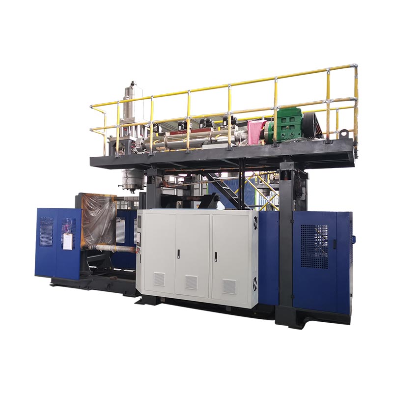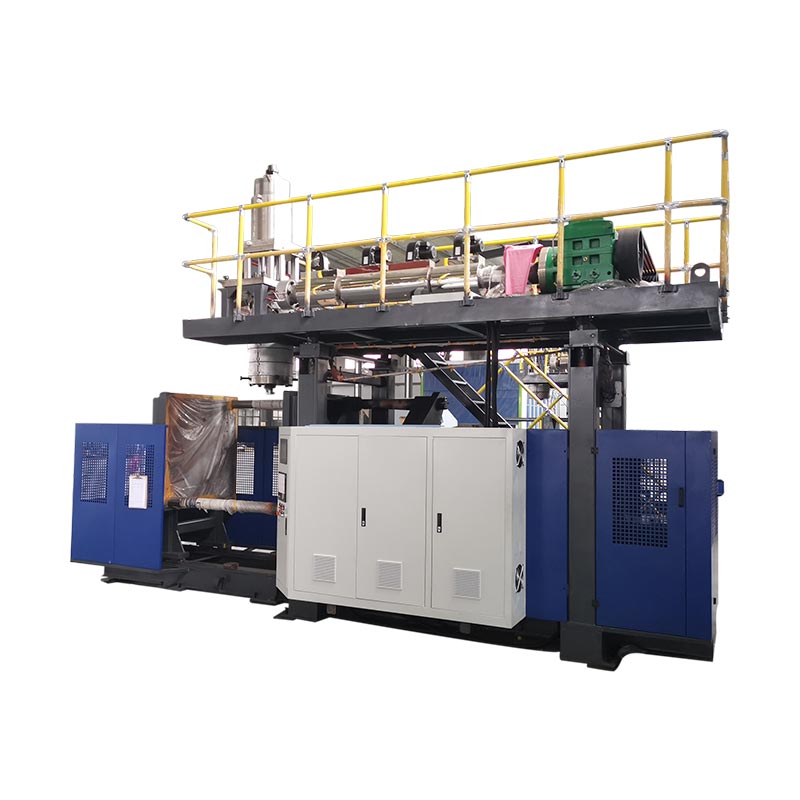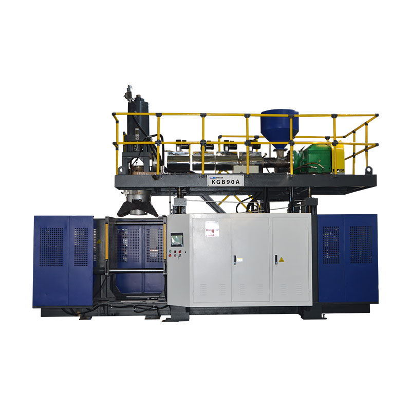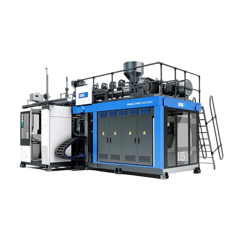
Configure the KGB110A from a measured product sample, not from the 160L name alone. Record the part geometry, net weight, wall map, resin, trim and production target. Then use those inputs to check the mold envelope, gross parison demand, extrusion recovery, clamp requirement and factory utilities.
A 160 litre blow moulding machine can make very different products. A hollow road barrier has a broad projected area. A pontoon may have long draw zones and sealing requirements. A table panel can be wide but relatively shallow. One model name does not remove those differences.
The most useful starting point is often the object already on the buyer's desk. Measure it, weigh it and mark the areas that matter. That sample becomes the link between product design, tooling, machine configuration and the acceptance test.

The six-page sample file that should drive the project
Dimensioned part drawing, overall size, openings, inserts and assembly interfaces.
Net part weight, material grade, color, additives and allowed regrind.
Wall-thickness map with critical locations and product test requirements.
Trim map showing top flash, bottom tail, handle scrap and other losses.
Accepted output target, shift pattern, automation and downstream work.
Factory power, air, water, access, lifting and available cell space.
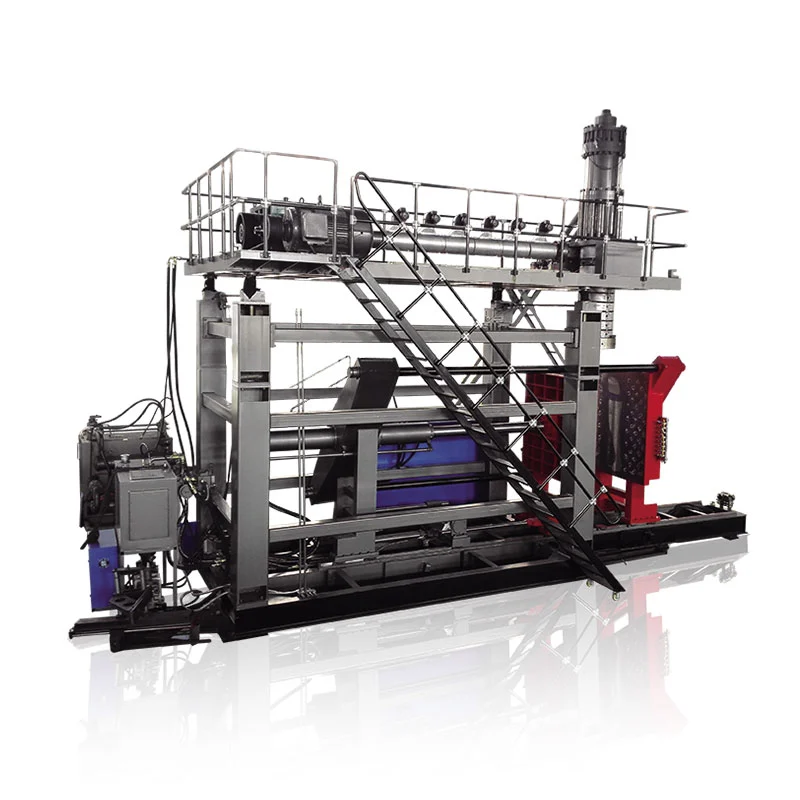
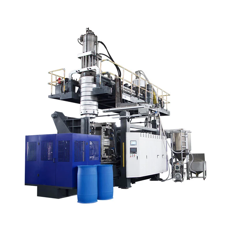
Published-data note: Kinggle's current page title and application text place the KGB110A in the 160L class. The same page currently shows 120 L in the summary and maximum-capacity table. This article follows the published 160L product positioning, but the exact ordered capacity must be confirmed in the quotation and technical agreement.
Start with the product sample, not the catalog label
The sample tells you where the machine decision can fail. Its outer dimensions affect the mold. Its weight and trim affect the accumulator. Its broad surfaces affect projected area. Deep corners and handles affect wall distribution. The cooling behavior affects cycle time and removal.
Volume is still useful. It helps place the project in a general machine range. Yet two products with the same enclosed volume may need different heads, clamps or mold openings. A bulky float can contain more air while using less resin than a dense technical panel with local ribs and thick mounting zones.
Do not rely on a competitor's finished part as the only source. If possible, add the original design file and the intended performance requirement. A copied sample may include wall thickness that compensates for an old mold or process. Repeating that wall without understanding its job can add weight without improving performance.
Kinggle's documented sales process begins with product photos, drawings, weight, size and material. It also asks for thickness, output and chemical-resistance requirements. That order is practical because the machine recommendation follows the product evidence.
The sample file should have one revision number. If the neck, handle, insert or overall length changes, update the file before the machine and mold are frozen. This avoids a project where the quotation fits an early sample but the production drawing no longer fits the quoted cell.
Build a sample dossier that can survive engineering review
Begin with basic measurements. Record overall length, width and height. Add opening diameters, neck finish, flange size, handle clearance and the position of any insert. Mark the parting line and visible pinch areas if the sample reveals them.
Weigh the complete product on a calibrated scale. Then separate any removable components that are not blow molded. A cap, plug, metal insert or foam filling should not be counted as molded plastic. Record the material identification method instead of assuming the polymer from appearance.
Wall thickness needs a location map. Number the points on a drawing or photo. Include corners, shoulder transitions, handles, base contacts, mounting zones and broad panels. A single average thickness hides the thin area that may control performance.
Next, write the product tests. A float, traffic barrier, furniture panel and industrial container do not have the same pass criteria. Use the buyer's actual drawing, regulatory requirement or internal test. Do not borrow a drop height, load or leak test from an unrelated product.
| Sample evidence | How to record it | Machine decision affected |
|---|---|---|
| Overall geometry | Dimensioned drawing or checked 3D file | Mold envelope, centerline, head position and removal path |
| Net molded weight | Weight without separately assembled parts | Starting point for gross parison mass |
| Wall distribution | Numbered locations with the chosen measurement method | Parison profile, shot distribution and trial criteria |
| Resin system | Grade, supplier, color, additives and regrind rule | Screw suitability, melt rate and processing window |
| Trim and flash | Expected top, bottom, handle and side scrap | Accumulator demand and regrind load |
| Functional tests | Named method, condition, sample size and pass limit | Mold design, cooling, wall targets and FAT scope |
| Accepted output | Good parts per hour or shift after inspection | Recovery rate, cooling, automation and downstream capacity |
A sample is evidence, not a complete specification. It may have aged, warped or absorbed chemicals. Use it to ask better questions, then place the approved drawing and test standard above the physical sample in the document hierarchy.
Read the KGB110A specification as a set of checks
The KGB110A product page publishes a 6.6 x 4.2 x 5.2 m machine size and 22 t machine weight. Its clamping section lists 760 kN, an 1100 x 1400 mm platen and a 1000 x 1400 mm maximum mold. The page also gives a 610 to 750 mm mold-thickness range.
For opening and movement, the page shows 600 to 1600 mm and a 600 mm moving stroke. These numbers need the mold assembly beside them. The useful question is whether the complete cooled part can release and leave the mold with the intended robot, inserts and trim still attached.
The extrusion section lists a 110 mm screw, 25 L/D ratio, 75 kW extruder motor and four heating zones. Published HDPE melting capacity is 160 to 200 kg/h. That range belongs to the page's HDPE wording. It does not prove the same rate for another material or formulation.
The head section publishes 12(20) L accumulator capacity and 9(15) kg PE accumulator weight. It also lists a 450(600) mm maximum die-pin diameter. Parenthetical values can reflect configuration choices, but the page does not define the rule. The proposal must state the selected head, die tooling and resin basis.
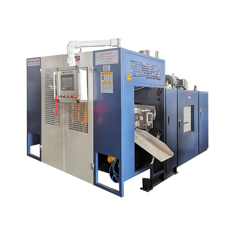
The page describes the standard model with a MOOG 100 thickness controller, robot arm and bottom blowing system. These are first-party published statements. The quotation should still name each supplied item, its interface and any project-specific change.
Factory reading: do not copy the table into a purchase order without its questions. Put the sample measurement, mold drawing or utility calculation beside every specification that it is meant to satisfy.
Translate the product shape into mold fit and removal space
The product drawing becomes a mold only after adding shrinkage strategy, cavity steel, cooling, pinch-off, vents, neck tooling and mounting. The resulting assembly can be much larger than the product. A part that looks comfortable inside a 1000 x 1400 mm limit may become tight once connections and moving devices are added.
Check width, height and installed thickness separately. Use the complete assembly, including backing plates and adapters. Confirm the mounting pattern against the 1100 x 1400 mm platen reference. Show water, hydraulic, pneumatic and electrical connections in their installed positions.
Opening space is a motion problem. A table panel may need to clear deep ribs. A barrier may leave the cavity at an angle. A pontoon can remain flexible while hot and may need support during take-out. The robot grip and part rotation need their own swept envelope.
Plan the mold-change route at the same time. The KGB110A page gives a 22 t machine weight but does not publish the allowable mold weight. Ask Kinggle for the final mold-weight limit, lifting points and general arrangement drawing. Then verify the plant crane, hook height and approach.
Mold cooling can control the whole cycle. Large surfaces need balanced circuits, while thick features may require focused cooling. The extrusion blow molding mold guide covers pinch-off, venting and circuit planning in more detail.
Calculate gross parison demand before choosing the head
The accumulator must deliver all material that leaves the die during one molding event. Finished product weight is only one part. The head also feeds flash, tails, handle scrap and any material that the trimming process removes.
Gross parison mass = net molded product + flash and trim + documented process allowance
Use measured or mold-derived values. There is no universal scrap percentage for floats, barriers, furniture and technical parts.
Kinggle publishes 9(15) kg as the PE accumulator-weight line for KGB110A. Treat it as a head and material reference, not finished-product capacity. PE grade, melt temperature, recycled content and die setting can change usable behavior. Another resin requires its own review.
Parison length matters with mass. A long parison can sag or stretch before the mold closes. A wide die may reduce the draw needed around the product but can change head and tooling requirements. Record the die size, programmed gap, extrusion time and parison position during the trial.
Gross demand also affects regrind. Heavy flash may fit the accumulator while creating a large scrap stream. The granulator, conveying and blending system must keep up. If regrind returns to the product, its percentage and contamination controls belong in the approved formulation.
Leave control range for profile correction. A head running at its practical edge may have little room for thicker corners or a longer parison. The trial should show stable gross mass, acceptable cushion and repeatable parison placement over a defined sample window.
Turn the wall map into a controlled parison profile
The wall map says where the product needs material. The parison profile says when the die gap should change as the parison leaves the head. Connecting those two records is more useful than copying a profile from a different part.
Number the wall locations on the sample drawing. After each trial, cut or measure the same locations in the same order. Record part weight and profile revision with every group. If several settings change at once, the team loses the reason for the result.
The KGB110A page names a MOOG 100 thickness controller. A Moog DigiPack III manual hosted by Kinggle explains a controller method that stores product files and relates programmed wall thickness to machine position. It is useful process evidence, but it does not identify the exact controller interface supplied on every KGB110A.
A profile cannot fix every defect. The die and mandrel geometry, head centering, melt temperature, parison swell and mold timing still matter. If the parison enters the mold off-center, adding material may hide the symptom while increasing weight.
Once the part passes, save the complete recipe. Include material, color, temperatures, shot setting, profile file, blowing, cooling and mold revision. The parison programming guide provides a fuller tuning sequence.
Match extrusion recovery to cooling and accepted output
The public table lists 160 to 200 kg/h as the KGB110A HDPE melting-capacity range. The production question is whether the selected screw can refill the accumulator before the next shot while maintaining stable melt quality. A maximum brochure rate cannot answer that by itself.
Calculate gross hourly demand from the complete parison. Use the planned molding events per hour and active outlets. Then compare the result with the tested melt rate for the actual resin, color and regrind condition.
Gross material demand, kg/h = gross parison mass x molding events per hour x active parisons per event
The KGB110A page lists 320 pcs/h, but labels it dry cycle. Dry cycle is a machine-motion reference. Product output includes accumulator recovery, parison formation, blowing, cooling, exhaust, opening, take-out, trimming and quality losses.
Large parts often spend much of the cycle cooling. That time can allow the extruder to refill the head. If better mold cooling shortens the cycle, the required melt rate rises. Cycle optimization must therefore check recovery and wall quality, not only mold temperature.
Report accepted parts per hour after the agreed checks. Keep dry cycle, gross cycles, rejects and stops in separate columns. The cycle-time optimization guide shows how to build a stage-by-stage time budget.
Check 760 kN against projected area and process pressure
Kinggle publishes 760 kN clamping force for the KGB110A. That number becomes useful only beside the cavity's projected area and the agreed internal pressure. Projected area is the cavity silhouette on the parting plane. It is not container volume or surface area.
A broad barrier or tabletop can create significant separating load even when it is shallow. A deep but narrow float may behave differently. Multi-cavity or multi-part layouts increase the total projected area seen by the clamp.
The product page lists 0.8 MPa blow pressure. Use the actual production window in the calculation. Mold venting, melt temperature, surface detail and wall thickness can change the needed pressure. The factory test should record set pressure and available machine-inlet pressure.
Flash condition is useful evidence. Growing flash can point to excessive separating force, worn pinch areas, alignment problems or excess material. Do not correct every flash problem by increasing clamp force. Inspect the mold and process together.
The machine supplier and mold supplier should approve one calculation. Put projected area, process pressure, clamp requirement and the assumed factor in the technical file. This prevents two separate approvals that rely on different assumptions.
Check the calculation again if the cavity layout changes. Adding a second part, moving the parting line or enlarging a panel can change projected area. Inserts and side actions may also change how the mold reacts. The final mold drawing, rather than an early product sketch, should close this check.
Define the material layers instead of relying on a feature phrase
The KGB110A page says the platform can provide single-layer products and can also construct double-layer or multi-layer structures. The same public specification table lists one 110 mm screw and one 75 kW extruder motor. A multi-layer project therefore needs a configuration drawing beyond the standard table.
Start with the product reason for another layer. It may be color placement, recycled core material or a functional barrier. State the material in each layer and the target ratio. Check compatibility, processing temperatures and the allowed variation.
Then request the melt-path diagram. It should identify every extruder, adapter, head channel and control point. The proposal should also show motor sizes, heating loads, material handling and the revised utility total. A generic “multi-layer” label does not define this equipment.
Changeover work grows with each material path. Purge volume, cleaning access, color sequence and scrap segregation affect operating time. If the product does not need multiple layers, the extra system may add work without creating buyer value.
Single-layer direction
Use one defined resin stream when the product performance, color and recycling plan can be met with one wall structure.
Multi-layer direction
Request a project-specific co-extrusion configuration when each layer has a documented function and acceptance range.
Kinggle's multi-layer co-extrusion guide explains layer roles and the questions that belong in the RFQ.
Plan the complete cell around a 22 t machine
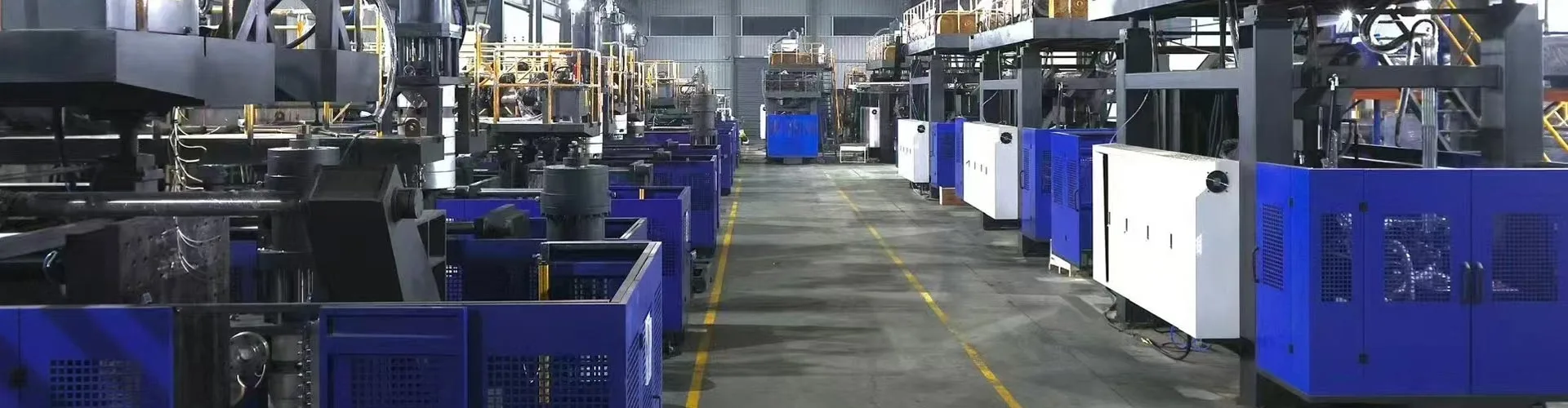
The published machine dimensions are 6.6 x 4.2 x 5.2 m. The machine weight is 22 t. These values start the plant layout. They do not include service clearance, stairs, mold handling, resin equipment, compressor, cooling system, take-out or downstream finishing.
Check the vertical path first. The building needs enough height for the machine, platform access and planned lifting. Mark the route for the die head and extruder components if maintenance requires overhead removal. Confirm the crane capacity and hook reach from the final drawing.
The KGB110A page publishes 0.3 MPa and 120 L/min for cooling water. The project sheet also needs inlet temperature, return limit, water quality, filtration and circuit scope. A flow number without temperature cannot size the cooling system.
For compressed air, the page lists 0.8 MPa and 1.8 m³/min. Confirm peak and average demand, receiver sizing, dew point, filtration and connection size. Large blowing events can pull pressure down when the header is undersized.
The page labels 52 to 60 kW as average energy consumption. Because kW is power, treat this as a published operating-power reference. Do not convert it into kWh per part. EUROMAP 46.2 ties product-related energy measurement to a given machine, mold and product under stable conditions.
The factory utility guide covers electrical boundaries, air, water, civil work and access. Use the final general arrangement drawing rather than the public envelope for installation approval.
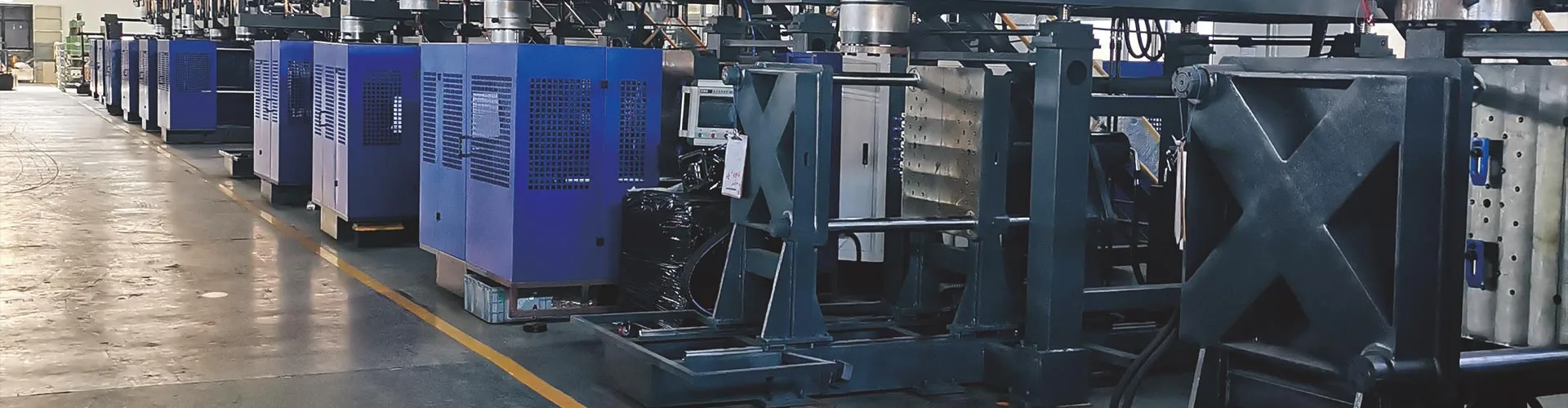
Prove the configuration with a traceable product trial
A factory trial should recreate the product job described in the sample file. The approved mold, resin and major options need to be present. If a substitute is used, record the difference and limit the conclusions accordingly.
Plan the sample sequence before running. Number parts in molding order. Define when stable production begins and how long the measurement window lasts. EUROMAP 46.2 requires stable machine conditions for its product-related energy method and documents product quality as part of the test context.
- Identify the configuration. Record machine serial number, head option, die tooling, mold revision, controller and installed automation.
- Verify the formulation. Record resin grade, supplier, color, additives and regrind content from the actual trial material.
- Capture the recipe. Save temperatures, shot settings, wall profile, blow settings, cooling conditions and automation timing.
- Close the mass balance. Weigh the product, every trim stream and the complete gross shot. Compare it with the quoted head basis.
- Measure the wall map. Use the numbered locations and agreed method. Keep the readings linked to each sample number.
- Run functional checks. Apply only the product-specific tests and limits written in the approved requirement.
- Count output honestly. Separate dry cycle, gross cycles, accepted parts, rejects and stops over the agreed period.
- Record utilities. Measure power, air and water at defined boundaries while the accepted product is being made.
- Close open items. Give each deviation an owner, corrective action, evidence requirement and due date.
Do not select only the best part for the report. Keep a sequence that shows variation. If the recipe changes, begin a new sample group. This separates process development from acceptance evidence.
Agree on the measuring tools before the test. Record scale resolution, thickness method and calibration status where they affect the result. Use the same tools for the sample sequence. If the buyer and supplier measure with different methods, compare those methods before deciding that the parts disagree.
A failed result needs context. Keep the related settings, alarm history, sample number and inspection record. A corrected part can prove the repair, but it should not erase the earlier deviation. This history helps the team decide whether the fix is stable or temporary.
Store raw data, photos, recipe exports and signed summaries together. The factory acceptance test guide provides a broader protocol for machine, product and document checks.
Use four gates to decide whether KGB110A fits
The KGB110A belongs on the shortlist when four evidence gates close. First, the mold fits the platen, envelope, thickness range and movement. Second, the selected head can deliver the gross parison with useful control range. Third, extrusion recovery supports the target cycle with the actual material. Fourth, the factory can supply the required utilities and handling.
A 160L label cannot replace any gate. A long part may fail the mold check. A heavy part may fail the shot check. A short cycle may fail the recovery check. A factory with limited height may fail the installation check.
Move down a machine range when the product and mold are much smaller and the larger platform adds no useful capacity. Move up or request another configuration when gross shot, mold space or clamp demand exceeds the proven range. The KGB100B 120L guide provides the adjacent lower-range engineering checks.
Finish the choice with a signed requirement matrix. Each line should name the buyer's input, the proposed configuration and the evidence that will prove compliance. Unknown items should remain open rather than being replaced with a brochure assumption.
The machine model is then the result of the product file. That order gives the mold designer, machine builder and buyer one set of facts to work from.
Frequently asked questions
What products is the KGB110A 160L blow molding machine intended for?
Kinggle's product page lists barrels, furniture, floats, pontoons, toys, auto parts and traffic barriers. These are application families. The specific product still needs checks for mold fit, gross parison mass, clamp demand, material, cooling and removal.
Why should I send a physical sample as well as a drawing?
The drawing defines the approved geometry, while the sample helps the engineering team inspect weight, parting line, trim, wall distribution and handling. Use both when possible. The drawing and written tests should control if the sample differs from the current design.
Is 320 pcs/h the production output of KGB110A?
No. The KGB110A page labels 320 pcs/h as dry cycle. Accepted output must include extrusion recovery, parison formation, blowing, cooling, take-out, trimming, rejects and counted stops with the production mold and resin.
Can a 15 kg finished PE part run on KGB110A?
The public table shows 9(15) kg as a PE accumulator-weight reference, not finished-product capacity. Gross parison mass includes the product and all flash or trim. Confirm the selected head, resin basis and operating margin, then prove the result in the product trial.
Does the standard KGB110A make multi-layer products?
The product description mentions single-layer and multi-layer solutions, while the public table lists one screw and one extruder motor. A multi-layer project needs a separate melt-path drawing, extruder list, head configuration, layer-ratio range and revised utility sheet.
What should be included in a KGB110A inquiry?
Send the product drawing, sample photos, dimensions, net weight, wall map, resin, trim estimate, quality tests, accepted output target, mold data and factory utilities. Kinggle can then confirm the head, mold space, extrusion arrangement and acceptance plan.
Send the product evidence, not only a volume
Share the sample file, mold information, output target and plant conditions with Kinggle. The project team can use those facts to confirm the KGB110A configuration and define a product-based trial.
Request a KGB110A configuration reviewSources and review basis
- Kinggle, 160L Accumulate Blow Molding Machine, model KGB110A. Product positioning, specifications and stated applications, checked September 15, 2026.
- Kinggle Sales Process. Product-information request and stated inspection workflow, checked September 15, 2026.
- Moog DigiPack III instruction manual hosted by Kinggle. Stored product files and programmed wall-thickness control for accumulator or continuous machines.
- EUROMAP 46.2, Extrusion Blow Moulding Machines, Determination of Product Related Energy Consumption. Version 1.0, January 2014.
Editorial note: Kinggle is the manufacturer and publisher of this guide. Product data is presented as first-party published information. The signed project specification and witnessed trial should control the ordered machine.